Esta versão pode conter edições incorretas. Mude para o último instantâneo verificado.
O que você precisa
-
-
Desligue o seu iPhone antes de começar a desmontagem.
-
Remova os dois parafusos pentalobe de 3,5 mm da borda inferior do iPhone.
-
-
-
Meça 3 mm a partir da ponta e marque a palheta com um marcador permanente.
-
-
-
Coloque tiras sobrepostas de fita adesiva transparente sobre a tela do iPhone até que toda a superfície fique coberta.
-
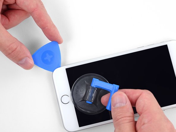
Se não conseguir fazer com que a ventosa grude nas próximas etapas, dobre um pedaço de fita adesiva resistente (como fita adesiva vedante) na forma de uma pega e levante a tela com ela.
-
-
-
Puxe a pega azul para trás para destravar os braços do Anti-Clamp.
-
Deslize os braços pela borda esquerda ou direita do seu iPhone.
-
Posicione as ventosas próximo à borda inferior do iPhone, diretamente acima do botão home, - uma pela dianteira e a outra pela traseira.
-
Aperte as ventosas uma contra a outra para aplicar sucção na área desejada.
-
-
-
Puxe a pega azul para a frente para travar os braços.
-
Gire a pega 360 graus no sentido horário até que as ventosas comecem a se esticar.
-
Certifique-se de que as ventosas permaneçam alinhadas uma com a outra. Se elas começarem a ficar desalinhadas, solte um pouco as ventosas e realinhe os braços.
-
-
-
Aqueça uma bolsa térmica iOpener e passe-a pelos braços do Anti-Clamp.
-
Dobre a bolsa térmica iOpener de modo que ela fique sobre a borda inferior do iPhone.
-
Aguarde um minuto para que o adesivo tenha a chance de se soltar e apresentar um vão para a abertura.
-
Insira uma palheta de abertura sob a tela quando o Anti-Clamp tiver formado um vão grande o suficiente.
-
Pule as próximas três etapas.
-
-
-
Use um secador de cabelo ou prepare uma bolsa térmica iOpener e aplique-o(a) na borda inferior do iPhone por cerca de 90 segundos para amolecer o adesivo que se encontra por baixo.
-
-
-
Este passo não foi traduzido. Ajude a traduzi-lo
-
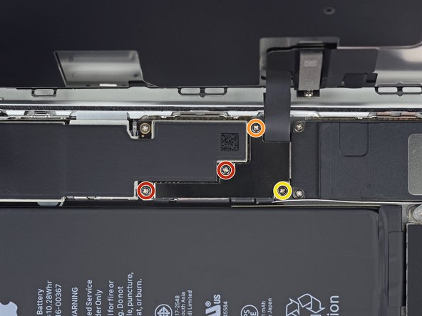
Remove four Phillips (JIS) screws securing the lower display cable bracket to the logic board, of the following lengths:
-
Two 1.3 mm screws
-
One 1.4 mm screw
-
One 2.7 mm screw
-
-
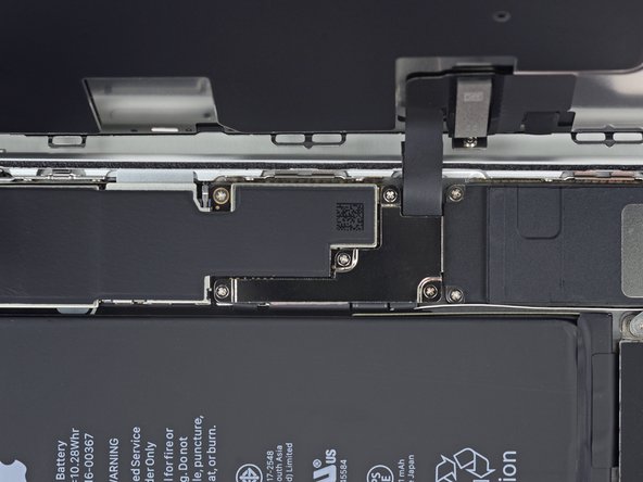
Este passo não foi traduzido. Ajude a traduzi-lo
-
Use the point of a spudger to pry the battery connector up from its socket on the logic board.
-
Bend the connector cable up slightly to prevent it from accidentally making contact with the socket and providing power to the phone during your repair.
-
-
Este passo não foi traduzido. Ajude a traduzi-lo
-
Use the tip of a spudger or a fingernail to disconnect the large lower display connector by prying it straight up from its socket.
-
-
Este passo não foi traduzido. Ajude a traduzi-lo
-
Disconnect the second lower display cable connector, directly behind the one you disconnected in the previous step.
-
-
Este passo não foi traduzido. Ajude a traduzi-lo
-
Remove the two tri-point Y000 screws securing the bracket over the front panel sensor assembly connector:
-
One 1.0 mm screw
-
One 1.2 mm screw
-
-
Este passo não foi traduzido. Ajude a traduzi-lo
-
Remove the bracket covering the front panel sensor assembly connector.
-
-
Este passo não foi traduzido. Ajude a traduzi-lo
-
Use the tip of a spudger or a fingernail to disconnect the front panel sensor assembly connector from its socket.
-
-
Este passo não foi traduzido. Ajude a traduzi-lo
-
Remove the four Y000 screws securing the bracket over the home/Touch ID sensor:
-
One 1.2 mm screw
-
Three 1.3 mm screws
-
-
Este passo não foi traduzido. Ajude a traduzi-lo
-
Remove the bracket that secures the home/Touch ID sensor.
-
-
Este passo não foi traduzido. Ajude a traduzi-lo
-
Pry under the left edge of the home button cable connector to disconnect it from its socket.
-
-
Este passo não foi traduzido. Ajude a traduzi-lo
-
Flip the display assembly over. Use a hairdryer or prepare an iOpener and apply it to the lower edge of the display for about 90 seconds in order to soften up the adhesive underneath.
-
-
Este passo não foi traduzido. Ajude a traduzi-lo
-
Use an opening pick to gently separate the adhesive holding the home/Touch ID sensor cable to the back side of the display panel.
-
-
Este passo não foi traduzido. Ajude a traduzi-lo
-
Remove the home/Touch ID sensor assembly by lifting it through the front side of the display.
-


Cancelar: não concluí este guia.
54 outras pessoas executaram este guia.


7 comentários
aiuto mi son cadute e quindi perso
sensore home/Touch ID Una vite da 1,2 mm Tre viti da 1,3 mm
dove le trovo?
Every time I have tried to transfer the home button from the broken screen to the replacement LCD - the home button has not worked. No tears in the cable. The connector is attached. Screw isn’t too tight. What could I be missing?
ATTENTION: Don’t screw in that one screw over the home button too much, or the button breaks! I just found one proper explanation for it in this YouTube video (https://www.youtube.com/watch?v=rDVnp90a...). Basically, that one screw that goes over the Home button should not be tightened too much, so that the metal plate doesn't bend (which it did for me).
This was truely helpful.
Anybody have the issue where the button works when the phone is in 2 pieces, but when you assemble the screen onto the phone body, the button no longer responds after a restart??
Power on phone while in 2 pieces -> home button is working
Attach screen to phone body -> home button is still working
Restart phone with phone assembled -> home button not responding