Esta versão pode conter edições incorretas. Mude para o último instantâneo verificado.
O que você precisa
-
Este passo não foi traduzido. Ajude a traduzi-lo
-
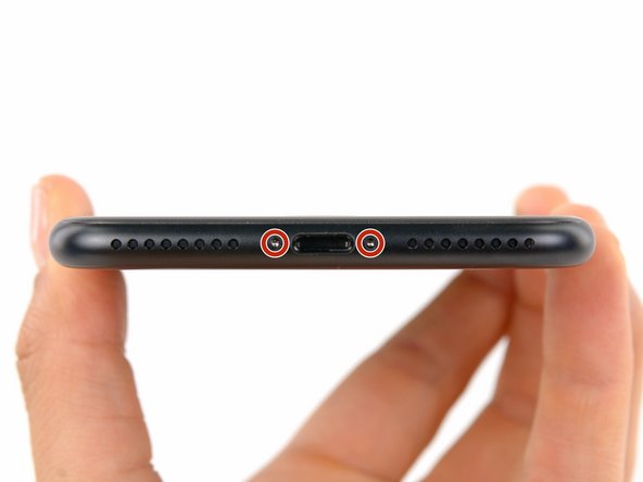
Power off your iPhone before beginning disassembly.
-
Remove the two 3.4 mm pentalobe screws at the bottom edge of the iPhone.
-
-
-
Meça 3 mm a partir da ponta e marque a palheta com um marcador permanente.
-
-
-
Puxe a pega azul para trás para destravar os braços do Anti-Clamp.
-
Deslize os braços pela borda esquerda ou direita do seu iPhone.
-
Posicione as ventosas próximo à borda inferior do iPhone, diretamente acima do botão home - uma pela dianteira e a outra pela traseira.
-
Aperte as ventosas uma contra a outra para aplicar sucção na área desejada.
-
-
-
Puxe a pega azul para a frente para travar os braços.
-
Gire a pega 360 graus no sentido horário até que as ventosas comecem a se esticar.
-
Certifique-se de que as ventosas permaneçam alinhadas uma com a outra. Se elas começarem a ficar desalinhadas, solte um pouco as ventosas e realinhe os braços.
-
-
-
Aqueça uma bolsa térmica iOpener e passe-a pelos braços do Anti-Clamp.
-
Dobre a bolsa térmica iOpener de modo que ela fique sobre a borda inferior do iPhone.
-
Aguarde um minuto para que o adesivo tenha a chance de se soltar e apresentar um vão para a abertura.
-
Insira uma palheta de abertura no vão.
-
Pule as próximas três etapas.
-
-
-
O aquecimento da borda inferior do iPhone ajudará a amolecer o adesivo que prende a tela, facilitando a abertura.
-
Use um secador de cabelo ou prepare uma bolsa térmica iOpener e aplique-o(a) na borda inferior do iPhone por cerca de 90 segundos para amolecer o adesivo que se encontra por baixo.
-
-
-
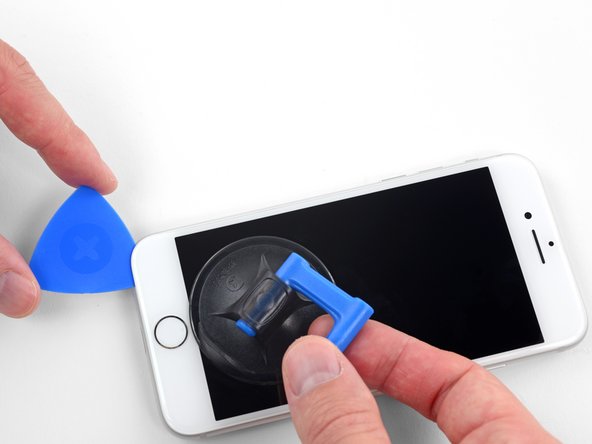
Aplique uma ventosa de sucção na metade inferior do painel dianteiro, imediatamente acima do botão home.
-
-
-
Este passo não foi traduzido. Ajude a traduzi-lo
-
Remove the following four tri-point Y000 screws securing the lower display cable bracket to the logic board:
-
Three 1.2 mm screws
-
One 2.6 mm screw
-
-
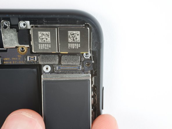
Este passo não foi traduzido. Ajude a traduzi-lo
-
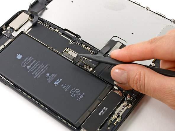
Use the point of a spudger to lift the battery connector out of its socket on the logic board.
-
-
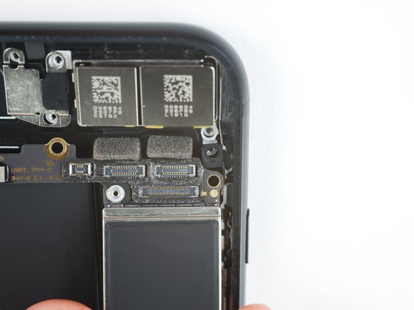
Este passo não foi traduzido. Ajude a traduzi-lo
-
Use the flat end of a spudger or a fingernail to disconnect the two lower display connectors by prying them straight up from their sockets on the logic board.
-
-
Este passo não foi traduzido. Ajude a traduzi-lo
-
Remove the three tri-point Y000 screws securing the bracket over the front panel sensor assembly connector:
-
One 1.3 mm screw
-
Two 1.0 mm screws
-
Remove the bracket.
-
-
Este passo não foi traduzido. Ajude a traduzi-lo
-
Disconnect the front panel sensor assembly connector from its socket on the logic board.
-
-
Este passo não foi traduzido. Ajude a traduzi-lo
-
Remove three Phillips screws securing the antenna component:
-
Two 1.3 mm screws
-
One 1.2 mm screw
-
-
Este passo não foi traduzido. Ajude a traduzi-lo
-
Remove the 1.3 mm Phillips screw securing the antenna component to the top edge of the rear case.
-
-
Este passo não foi traduzido. Ajude a traduzi-lo
-
Tilt the antenna component up towards the top of the phone.
-
Slide the screw boss down and out of its recess.
-
-
Este passo não foi traduzido. Ajude a traduzi-lo
-
Insert a SIM card eject tool or a paperclip into the small hole in the SIM card tray.
-
Press firmly to eject the tray.
-
-
Este passo não foi traduzido. Ajude a traduzi-lo
-
Use an iFixit opening tool or a fingernail to disconnect the dual camera cable connectors by prying them straight up from their sockets.
-
-
Este passo não foi traduzido. Ajude a traduzi-lo
-
Remove the two screws securing the rear-facing camera bracket:
-
One 1.6 mm Phillips screw
-
One 2.2 mm standoff screw
-
-
Este passo não foi traduzido. Ajude a traduzi-lo
-
Remove the bracket covering the rear-facing camera.
-
-
Este passo não foi traduzido. Ajude a traduzi-lo
-
Remove the two 1.3 mm Phillips screws securing the upper cable bracket.
-
-
Este passo não foi traduzido. Ajude a traduzi-lo
-
Remove the two 1.3 mm Phillips screws securing the grounding clip at the top left edge of the logic board.
-
-
Este passo não foi traduzido. Ajude a traduzi-lo
-
Remove the 1.3 mm Phillips screw securing the antenna flex cable to the top edge of the iPhone's rear case.
-
Remove the remaining Phillips screw from the antenna flex cable.
-
-
Este passo não foi traduzido. Ajude a traduzi-lo
-
Use a fingernail or the sharp end of an iFixit opening tool to pry up and disconnect the antenna flex cable connector from the logic board.
-
-
Este passo não foi traduzido. Ajude a traduzi-lo
-
Slide the flat edge of a spudger underneath the antenna flex cable to separate the adhesive holding it in place.
-
-
Este passo não foi traduzido. Ajude a traduzi-lo
-
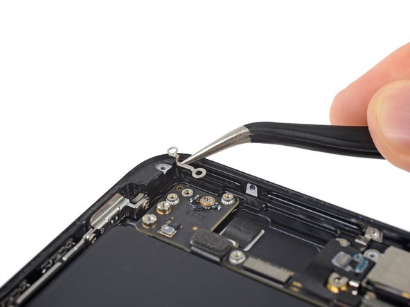
Tilt the antenna flex cable up toward the top of the iPhone.
-
Slide the screw boss down and out of its recess.
-
Remove the antenna flex cable.
-
-
Este passo não foi traduzido. Ajude a traduzi-lo
-
Use a thin pry tool or tweezers to carefully pry up and disconnect the two coaxial cable connectors from the logic board.
-
-
Este passo não foi traduzido. Ajude a traduzi-lo
-
Disconnect the two remaining ribbon cables from the logic board:
-
Disconnect the upper cable connector by prying from the top
-
Disconnect the Lightning port connector by prying along the outer edge
-
-
Este passo não foi traduzido. Ajude a traduzi-lo
-
Remove the seven screws securing the logic board:
-
One 1.3 mm Phillips screw
-
Two 2.1 mm standoff screws
-
One 2.0 mm standoff screw with a large head
-
One 2.0 mm standoff screw with a small head
-
Two 2.2 mm standoff screws
-
-
Este passo não foi traduzido. Ajude a traduzi-lo
-
Use the point of a spudger to push the SIM card eject plunger out of the logic board's way.
-
-
Este passo não foi traduzido. Ajude a traduzi-lo
-
Use the point of a spudger to carefully de-route the two coaxial cables from the small metal clip holding them to the logic board.
-
-
Este passo não foi traduzido. Ajude a traduzi-lo
-
Lift the logic board from the bottom edges and slide it toward the bottom of the iPhone to remove it.
-


Cancelar: não concluí este guia.
102 outras pessoas executaram este guia.


20 comentários
Can we use iphone 7+ 32gb board to a iphone 7+ 128 GB
You can purchase motherboard from this website.
It's really tough to install Board component but this guideline really helpful..