Esta versão pode conter edições incorretas. Mude para o último instantâneo verificado.
O que você precisa
-
Este passo não foi traduzido. Ajude a traduzi-lo
-
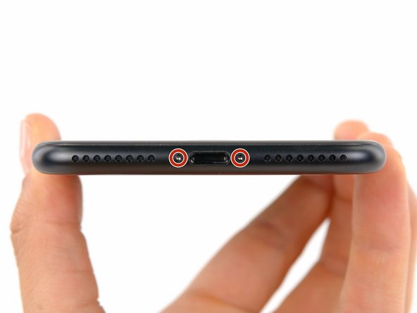
Power off your iPhone before beginning disassembly.
-
Remove the two 3.4 mm pentalobe screws at the bottom edge of the iPhone.
-
-
-
Meça 3 mm a partir da ponta e marque a palheta com um marcador permanente.
-
-
-
Puxe a pega azul para trás para destravar os braços do Anti-Clamp.
-
Deslize os braços pela borda esquerda ou direita do seu iPhone.
-
Posicione as ventosas próximo à borda inferior do iPhone, diretamente acima do botão home - uma pela dianteira e a outra pela traseira.
-
Aperte as ventosas uma contra a outra para aplicar sucção na área desejada.
-
-
-
Puxe a pega azul para a frente para travar os braços.
-
Gire a pega 360 graus no sentido horário até que as ventosas comecem a se esticar.
-
Certifique-se de que as ventosas permaneçam alinhadas uma com a outra. Se elas começarem a ficar desalinhadas, solte um pouco as ventosas e realinhe os braços.
-
-
-
Aqueça uma bolsa térmica iOpener e passe-a pelos braços do Anti-Clamp.
-
Dobre a bolsa térmica iOpener de modo que ela fique sobre a borda inferior do iPhone.
-
Aguarde um minuto para que o adesivo tenha a chance de se soltar e apresentar um vão para a abertura.
-
Insira uma palheta de abertura no vão.
-
Pule as próximas três etapas.
-
-
-
O aquecimento da borda inferior do iPhone ajudará a amolecer o adesivo que prende a tela, facilitando a abertura.
-
Use um secador de cabelo ou prepare uma bolsa térmica iOpener e aplique-o(a) na borda inferior do iPhone por cerca de 90 segundos para amolecer o adesivo que se encontra por baixo.
-
-
-
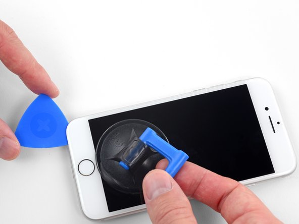
Aplique uma ventosa de sucção na metade inferior do painel dianteiro, imediatamente acima do botão home.
-
-
Este passo não foi traduzido. Ajude a traduzi-lo
-
Remove the following four tri-point Y000 screws securing the lower display cable bracket to the logic board:
-
Three 1.2 mm screws
-
One 2.6 mm screw
-
-
Este passo não foi traduzido. Ajude a traduzi-lo
-
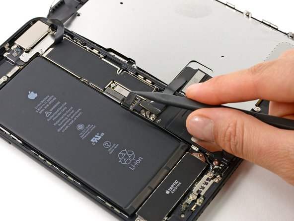
Use the point of a spudger to lift the battery connector out of its socket on the logic board.
-
-
Este passo não foi traduzido. Ajude a traduzi-lo
-
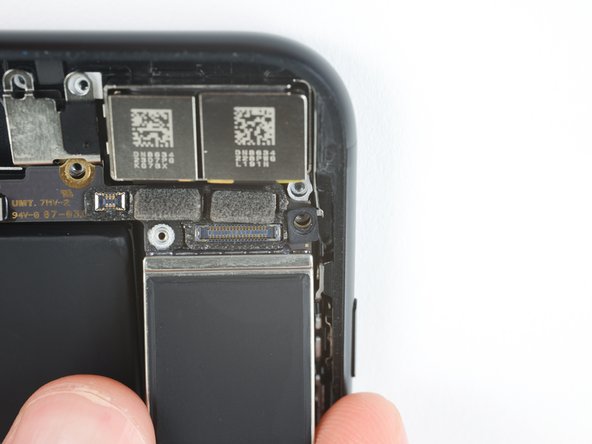
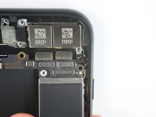
Use the flat end of a spudger or a fingernail to disconnect the two lower display connectors by prying them straight up from their sockets on the logic board.
-
-
Este passo não foi traduzido. Ajude a traduzi-lo
-
Remove the three tri-point Y000 screws securing the bracket over the front panel sensor assembly connector:
-
One 1.3 mm screw
-
Two 1.0 mm screws
-
Remove the bracket.
-
-
Este passo não foi traduzido. Ajude a traduzi-lo
-
Disconnect the front panel sensor assembly connector from its socket on the logic board.
-
-
-
Este passo não foi traduzido. Ajude a traduzi-lo
-
Remove three Phillips screws securing the antenna component:
-
Two 1.3 mm screws
-
One 1.2 mm screw
-
-
Este passo não foi traduzido. Ajude a traduzi-lo
-
Remove the 1.3 mm Phillips screw securing the antenna component to the top edge of the rear case.
-
-
Este passo não foi traduzido. Ajude a traduzi-lo
-
Tilt the antenna component up towards the top of the phone.
-
Slide the screw boss down and out of its recess.
-
-
Este passo não foi traduzido. Ajude a traduzi-lo
-
Insert a SIM card eject tool or a paperclip into the small hole in the SIM card tray.
-
Press firmly to eject the tray.
-
-
Este passo não foi traduzido. Ajude a traduzi-lo
-
Use an iFixit opening tool or a fingernail to disconnect the dual camera cable connectors by prying them straight up from their sockets.
-
-
Este passo não foi traduzido. Ajude a traduzi-lo
-
Remove the two screws securing the rear-facing camera bracket:
-
One 1.6 mm Phillips screw
-
One 2.2 mm standoff screw
-
-
Este passo não foi traduzido. Ajude a traduzi-lo
-
Remove the bracket covering the rear-facing camera.
-
-
Este passo não foi traduzido. Ajude a traduzi-lo
-
Remove the two 1.3 mm Phillips screws securing the upper cable bracket.
-
-
Este passo não foi traduzido. Ajude a traduzi-lo
-
Remove the two 1.3 mm Phillips screws securing the grounding clip at the top left edge of the logic board.
-
-
Este passo não foi traduzido. Ajude a traduzi-lo
-
Remove the 1.3 mm Phillips screw securing the antenna flex cable to the top edge of the iPhone's rear case.
-
Remove the remaining Phillips screw from the antenna flex cable.
-
-
Este passo não foi traduzido. Ajude a traduzi-lo
-
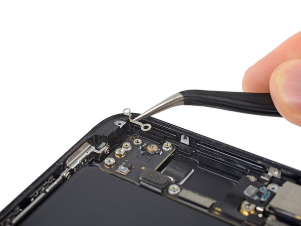
Use a fingernail or the sharp end of an iFixit opening tool to pry up and disconnect the antenna flex cable connector from the logic board.
-
-
Este passo não foi traduzido. Ajude a traduzi-lo
-
Slide the flat edge of a spudger underneath the antenna flex cable to separate the adhesive holding it in place.
-
-
Este passo não foi traduzido. Ajude a traduzi-lo
-
Tilt the antenna flex cable up toward the top of the iPhone.
-
Slide the screw boss down and out of its recess.
-
Remove the antenna flex cable.
-
-
Este passo não foi traduzido. Ajude a traduzi-lo
-
Use a thin pry tool or tweezers to carefully pry up and disconnect the two coaxial cable connectors from the logic board.
-
-
Este passo não foi traduzido. Ajude a traduzi-lo
-
Disconnect the two remaining ribbon cables from the logic board:
-
Disconnect the upper cable connector by prying from the top
-
Disconnect the Lightning port connector by prying along the outer edge
-
-
Este passo não foi traduzido. Ajude a traduzi-lo
-
Remove the seven screws securing the logic board:
-
One 1.3 mm Phillips screw
-
Two 2.1 mm standoff screws
-
One 2.0 mm standoff screw with a large head
-
One 2.0 mm standoff screw with a small head
-
Two 2.2 mm standoff screws
-
-
Este passo não foi traduzido. Ajude a traduzi-lo
-
Use the point of a spudger to push the SIM card eject plunger out of the logic board's way.
-
-
Este passo não foi traduzido. Ajude a traduzi-lo
-
Use the point of a spudger to carefully de-route the two coaxial cables from the small metal clip holding them to the logic board.
-
-
Este passo não foi traduzido. Ajude a traduzi-lo
-
Lift the logic board from the bottom edges and slide it toward the bottom of the iPhone to remove it.
-
-
Este passo não foi traduzido. Ajude a traduzi-lo
-
Remove the following two Phillips screws securing the barometric vent to the rear case:
-
One 2.9 mm screw
-
One 2.1 mm screw
-
-
Este passo não foi traduzido. Ajude a traduzi-lo
-
Gently push the barometric vent in the direction of the Taptic Engine to separate the adhesive securing it to the bottom edge of the iPhone.
-
-
Este passo não foi traduzido. Ajude a traduzi-lo
-
Pry up the Taptic Engine's ribbon cable connector to disconnect it.
-
-
Este passo não foi traduzido. Ajude a traduzi-lo
-
Remove the three 1.5 mm Phillips screws securing the Taptic Engine to the rear case.
-
-
Este passo não foi traduzido. Ajude a traduzi-lo
-
Carefully de-route the two coaxial cables from the metal bracket holding them to the side of the speaker.
-
-
Este passo não foi traduzido. Ajude a traduzi-lo
-
Remove the five Phillips screws securing the speaker:
-
Three 1.3 mm screws
-
One 2.3 mm screw
-
One 3.3 mm screw
-
-
Este passo não foi traduzido. Ajude a traduzi-lo
-
Remove the 2.9 mm Phillips screw at the top left of the Lightning port.
-
-
Este passo não foi traduzido. Ajude a traduzi-lo
-
Remove the spring contact underneath the screw you just removed.
-
-
Este passo não foi traduzido. Ajude a traduzi-lo
-
Remove the following three Phillips screws securing the Lightning connector:
-
Two 1.7 mm screws
-
One 2.8 mm screw
-
-
Este passo não foi traduzido. Ajude a traduzi-lo
-
Remove the two 1.2 mm Phillips screws securing the Lightning port to the bottom edge of the iPhone.
-
-
Este passo não foi traduzido. Ajude a traduzi-lo
-
Use the sharp edge of an iFixit Opening Tool to pry the two microphones free from the adhesive securing them in place.
-
-
Este passo não foi traduzido. Ajude a traduzi-lo
-
Slide an opening pick or thin pry tool underneath the top portion of the Lightning connector assembly flex cable, and begin separating it from the rear case.
-
-
Este passo não foi traduzido. Ajude a traduzi-lo
-
Continue separating the upper portion of the flex cable, being careful not to damage any other components along the way.
-
-
Este passo não foi traduzido. Ajude a traduzi-lo
-
Carefully slide your pick from the corner of the battery to the corner of the iPhone to separate the portion of the flex cable adhered to the outer frame.
-
-
Este passo não foi traduzido. Ajude a traduzi-lo
-
Slide your pick across the width of the iPhone to separate all the remaining strands of the flex cable from the rear case.
-
-
Este passo não foi traduzido. Ajude a traduzi-lo
-
Remove the Lightning connector assembly.
-
Use a plastic tool to scour any bits of adhesive residue from the rear case.
-
You can clean any remaining residue from the surface with isopropyl alcohol (90% concentration or greater) and a lint-free cloth. Wipe in one direction only, not back and forth.
-
Make sure the Lightning connector assembly is correctly positioned so that the two white dots on the iPhone's rear case show through the two circular cutouts in the Lightning flex cable. If they don't, the flex cable will remain misaligned and you won't be able to reconnect it to its socket on the logic board.
-


Cancelar: não concluí este guia.
193 outras pessoas executaram este guia.


41 comentários
NOTE TO ALL: When you put the port back in, LINE UP THE HOLES ON THE FRAME. If you don’t line up the holes perfectly on the cable (even if it’s off by a millimeter), the cable will NOT extend and plug into the logic board. It has to be perfect. You’re welcome :)
I have this issue but cant seem to get it to set properly? any ideas the po seems like it's in fine but wont connect to logic board
I feel like this is the most important piece of information on this entire guide. I drove myself mad disassembling and reassembling multiple iPhone 7/8 Plus devices with this exact issue.
Conrad -
So i did this and now my home button does not work. Any suggestions?
So far as I can tell, the only part of this procedure that affects the home button is when it’s disconnected from the board in step 14. I’d probably double-check those connectors to make sure they’re seated properly for a start. Check the sockets for dust/debris or pin damage. Inspect the cables for damage. While you’re troubleshooting, remember to always disconnect the battery first and reconnect it last. Good luck!