Esta versão pode conter edições incorretas. Mude para o último instantâneo verificado.
O que você precisa
-
-
Remova os dois parafusos Pentalobe P2 de 3,4 mm localizados na borda inferior do iPhone, dispostos ao lado do conector Lightning.
-
-
-
Puxe a pega azul para trás para destravar os braços do Anti-Clamp.
-
Deslize os braços pela borda esquerda ou direita do seu iPhone.
-
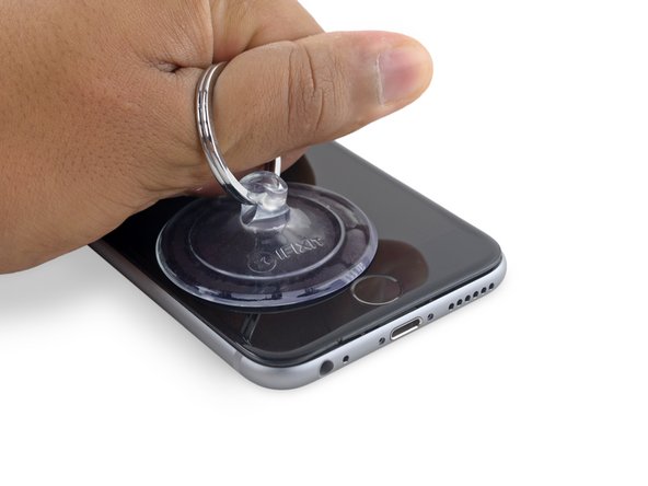
Posicione as ventosas próximo à borda inferior do iPhone, diretamente acima do botão home - uma pela dianteira e a outra pela traseira.
-
Aperte as ventosas uma contra a outra para aplicar sucção na área desejada.
-
-
Este passo não foi traduzido. Ajude a traduzi-lo
-
If you don't have an Anti-Clamp, follow the next three steps to use a suction handle.
-
Apply mild heat to the lower edge of the iPhone using an iOpener or hair dryer for about a minute.
-
-
-
Segure com cuidado o conjunto do display e eleve-o para abrir o telefone, usando os clipes na parte superior do painel dianteiro como uma dobradiça.
-
Abra o display a um ângulo de cerca de 90º e apoie-o em algo que o sustente enquanto você está trabalhando no telefone.
-
Engate uma faixa de elástico para fixar seguramente o display enquanto você trabalha. Isso previne uma tensão indevida nos cabos do display.
-
-
-
Remova os dois parafusos Phillips que seguram o suporte do conector da bateria:
-
Um parafuso de 2,9 mm
-
Um parafuso de 2,2 mm
-
-
-
Remova os seguintes quatro parafusos Phillips que seguram o suporte do cabo do display:
-
Três parafusos de 1,2 mm
-
Um parafuso de 2,8 mm
-
-
-
Este passo não foi traduzido. Ajude a traduzi-lo
-
Use the flat end of a spudger to disconnect the rear camera from its socket on the logic board.
-
-
Este passo não foi traduzido. Ajude a traduzi-lo
-
Remove the following two Phillips screws over the rear camera bracket:
-
One 1.6 mm screw
-
One 2.0 mm screw
-
-
Este passo não foi traduzido. Ajude a traduzi-lo
-
Insert a spudger to the side of the camera, between the rear case and the camera module.
-
Gently pry up on the camera to nudge it out from its housing.
-
-
Este passo não foi traduzido. Ajude a traduzi-lo
-
Insert a SIM card eject tool or a paperclip into the small hole in the SIM card tray.
-
Press to eject the tray.
-
-
Este passo não foi traduzido. Ajude a traduzi-lo
-
Remove the two 2.3 mm Phillips screws securing the upper component cable connector bracket.
-
-
Este passo não foi traduzido. Ajude a traduzi-lo
-
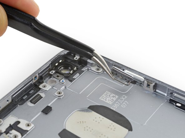
Remove the upper component cable connector bracket.
-
-
Este passo não foi traduzido. Ajude a traduzi-lo
-
Remove the following five Phillips screws securing the top left Wi-Fi antenna:
-
Two 1.5mm screws
-
One 2.3 mm screw
-
One 1.9 mm screw
-
One 2.0 mm screw
-
-
Este passo não foi traduzido. Ajude a traduzi-lo
-
Use the flat end of a spudger to disconnect the audio control cable from its socket on the logic board.
-
-
Este passo não foi traduzido. Ajude a traduzi-lo
-
Use the pointed tip of a spudger to disconnect the antenna cable from its socket on the upper right corner of the logic board.
-
-
Este passo não foi traduzido. Ajude a traduzi-lo
-
Use the pointed tip of a spudger to disconnect the antenna cable from its socket on the lower left corner of the logic board.
-
-
Este passo não foi traduzido. Ajude a traduzi-lo
-
Insert the flat end of a spudger underneath the Lightning connector ribbon cable. Lift up to disconnect it from its socket on the logic board.
-
-
Este passo não foi traduzido. Ajude a traduzi-lo
-
Gently pull up on the antenna cable to de-route it from the two clips on the right side of the logic board.
-
-
Este passo não foi traduzido. Ajude a traduzi-lo
-
Remove the 1.3 mm Phillips screw securing the NFC bracket to the logic board.
-
-
Este passo não foi traduzido. Ajude a traduzi-lo
-
Remove the following two Phillips screws:
-
One 2.5 mm screw at the top of the logic board
-
One 1.4 mm screw set into the upper edge of the rear case
-
-
Este passo não foi traduzido. Ajude a traduzi-lo
-
Remove the final three screws securing the logic board to the rear case:
-
One 1.9 mm Phillips screw
-
One 2.5 mm hex nut
-
One 1.8 mm Phillips screw
-
-
Este passo não foi traduzido. Ajude a traduzi-lo
-
Insert an opening pick below the lower edge of the logic board, between the board and the loudspeaker.
-
Use the opening pick to gently lift the logic board out of its housing.
-
Remove the logic board.
-
-
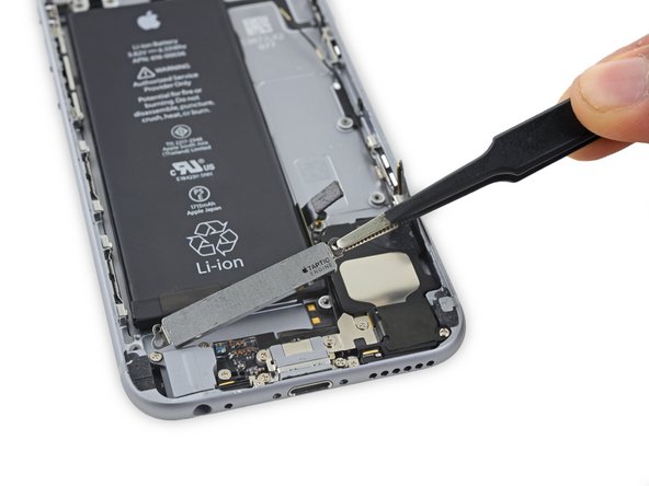
Este passo não foi traduzido. Ajude a traduzi-lo
-
Remove the two 1.5 mm Phillips screws holding the Taptic Engine in place.
-
Remove the Taptic Engine.
-
-
Este passo não foi traduzido. Ajude a traduzi-lo
-
Use tweezers to peel up the tips of the battery adhesive strips at the lower edge of the battery.
-
-
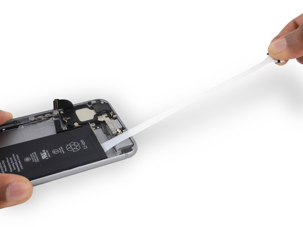
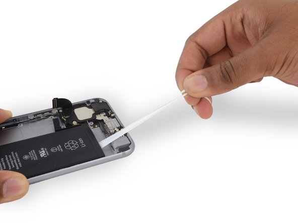
Este passo não foi traduzido. Ajude a traduzi-lo
-
Pull one of the adhesive strips straight out, towards the bottom of the iPhone.
-
For best results, pull the strip at a 60º angle or less.
-
Continue pulling until the strip is fully removed.
-
If one of the adhesive strips breaks under the battery during this procedure, and cannot be retrieved, remove the remaining strip, and then skip to Step 48.
-
-
Este passo não foi traduzido. Ajude a traduzi-lo
-
Repeat the previous step for the second adhesive strip.
-
-
Este passo não foi traduzido. Ajude a traduzi-lo
-
If you successfully removed all three adhesive strips, move on to the next step. Otherwise, you will need to pry the battery from the rear case.
-
Prepare an iOpener and apply it to the back of the rear case, directly over the battery. Alternatively, you can apply heat using a heat gun or hair dryer.
-
After about a minute, flip the phone over and use a plastic card to break up any remaining adhesive behind the battery.
-
-
Este passo não foi traduzido. Ajude a traduzi-lo
-
Remove the single 1.3 mm Phillips screw securing the flash bracket.
-
Remove the flash bracket.
-
-
Este passo não foi traduzido. Ajude a traduzi-lo
-
Use the flat end of a spudger to lift the flash out of its housing in the rear case.
-
-
Este passo não foi traduzido. Ajude a traduzi-lo
-
Remove the following five Phillips screws:
-
Two 2.5 mm screws set into the left edge of the rear case
-
One 2.1 mm Phillips #000 screw set into the left edge of the rear case
-
Two 2.1 mm screws set into the right edge of the rear case
-
-
Este passo não foi traduzido. Ajude a traduzi-lo
-
Use the pointed tip of a spudger to gently separate the microphone from the rear case.
-
-
Este passo não foi traduzido. Ajude a traduzi-lo
-
Slide an opening pick between the upper component cable and the rear case.
-
Gently separate the cable from the rear case.
-
-
Este passo não foi traduzido. Ajude a traduzi-lo
-
Continue pushing the opening pick under the cable until it fully separates from the rear case.
-
-
Este passo não foi traduzido. Ajude a traduzi-lo
-
If your replacement part did not come with the mute switch cover, you will need to remove the switch cover and transfer It.
-
Use the flat end of the spudger to press down and hold the old bracket firmly in place.
-
Use tweezers or your fingers to carefully rock the switch cover such that the switch cover pins swing out of their clips.
-
Lift the switch cover straight up.
-
-
Este passo não foi traduzido. Ajude a traduzi-lo
-
Grasp the metal bar on the back of the power button cover.
-
Remove the power button cover.
-


Cancelar: não concluí este guia.
33 outras pessoas executaram este guia.
