Esta versão pode conter edições incorretas. Mude para o último instantâneo verificado.
O que você precisa
-
Este passo não foi traduzido. Ajude a traduzi-lo
-
Use a spudger to disconnect the Lightning connector ribbon cable from its socket on the logic board.
-
The Lightning connector cable is lightly adhered to a shield on the logic board. Use the flat end of a spudger to gently peel the cable up.
-
-
Este passo não foi traduzido. Ajude a traduzi-lo
-
Flip the Lightning connector cable up out of the way of the logic board.
-
-
Este passo não foi traduzido. Ajude a traduzi-lo
-
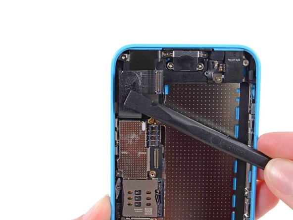
Disconnect the lower antenna connector from the base of the logic board.
-
-
Este passo não foi traduzido. Ajude a traduzi-lo
-
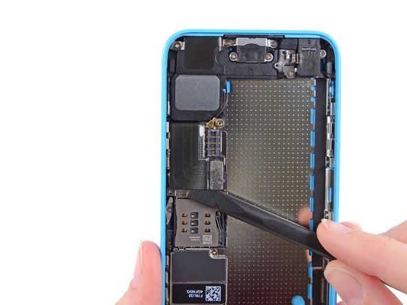
Use the flat end of a spudger to disconnect the audio control cable connector from its socket on the logic board.
-
Disconnect the rear-facing camera cable connector from its socket on the logic board.
-
-
-
Este passo não foi traduzido. Ajude a traduzi-lo
-
A small piece of tape may obscure the logic board grounding clip. If so, use a pair of tweezers to remove the tape.
-
-
Este passo não foi traduzido. Ajude a traduzi-lo
-
Remove the following screws securing the logic board grounding clip to the rear case:
-
1.2 mm Phillips #000 in the top side-wall
-
2.5 mm Phillips #000
-
-
Este passo não foi traduzido. Ajude a traduzi-lo
-
Use tweezers to remove the logic board grounding clip.
-
-
Este passo não foi traduzido. Ajude a traduzi-lo
-
Remove the following screws securing the logic board to the rear case:
-
Two 2.3 mm Phillips screws
-
Three 2.7 mm standoff screws
-
-
Este passo não foi traduzido. Ajude a traduzi-lo
-
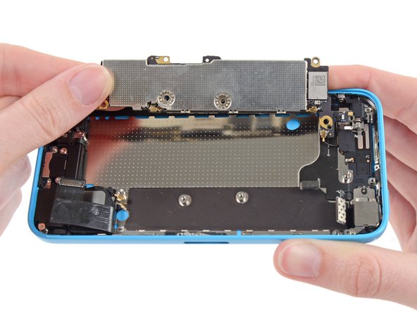
Holding the phone level, lift the bottom end of the logic board up enough to grasp it with your fingers.
-
Pull the logic board away from the rear-facing camera just enough to expose the gold contact cap under the top end of the board.
-
Remove the gold-colored contact cap from the threaded post in the rear case, and set it aside.
-
-
Este passo não foi traduzido. Ajude a traduzi-lo
-
Flip the logic board up toward the volume control buttons to expose the antenna connector.
-
-
Este passo não foi traduzido. Ajude a traduzi-lo
-
Disconnect the antenna connector from the back of the logic board.
-