Esta versão pode conter edições incorretas. Mude para o último instantâneo verificado.
O que você precisa
-
-
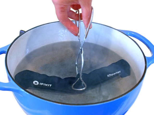
Encha uma panela ou frigideira com água suficiente para submergir completamente um iOpener.
-
Aqueça a água até ferver. Desligue o fogo.
-
Coloque um iOpener na água quente por 2 a 3 minutos. Certifique-se de que o iOpener esteja totalmente submerso na água.
-
Use um pegador para retirar o iOpener aquecido da água quente.
-
Seque bem o iOpener com uma toalha.
-
Sua bolsa térmica iOpener está pronta para o uso! Se precisar reaquecer o iOpener, aqueça a água até ferver, desligue o fogo e coloque o iOpener na água por 2 a 3 minutos.
-
-
Este passo não foi traduzido. Ajude a traduzi-lo
-
If your display glass is cracked, keep further breakage contained and prevent bodily harm during your repair by taping the glass.
-
Lay overlapping strips of clear packing tape over the iPad's display until the whole face is covered.
-
Do your best to follow the rest of the guide as described. However, once the glass is broken, it will likely continue to crack as you work, and you may need to use a metal prying tool to scoop the glass out.
-
-
Este passo não foi traduzido. Ajude a traduzi-lo
-
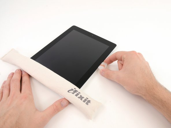
Lay the iOpener flat on the right edge of the iPad, smoothing it out so that there is good contact between the surface of the iPad and the iOpener.
-
Let the bag sit on the iPad for approximately 90 seconds before attempting to open the front panel.
-
-
Este passo não foi traduzido. Ajude a traduzi-lo
-
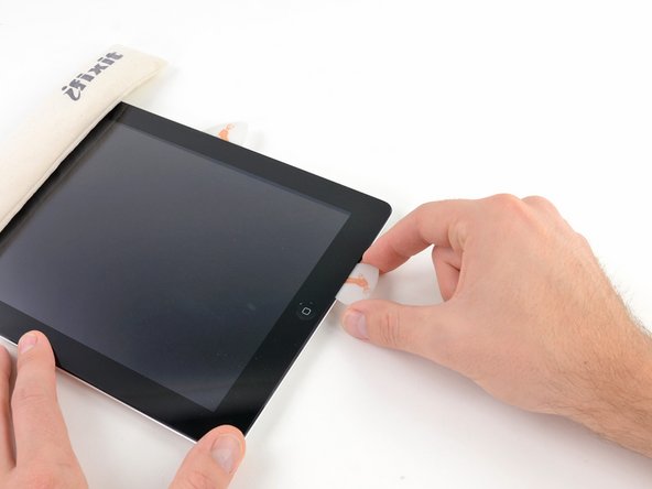
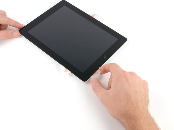
There is a small gap in the iPad's adhesive ring in the upper right corner of the iPad, approximately 2.0 inches (~5 cm) from the top of the iPad. You are going to exploit this weakness.
-
Align the tool with the mute button. Insert the tip of a plastic opening tool into the gap between the front glass and the plastic bezel. Just insert the very tip of the opening tool, just enough to widen the crack.
-
-
Este passo não foi traduzido. Ajude a traduzi-lo
-
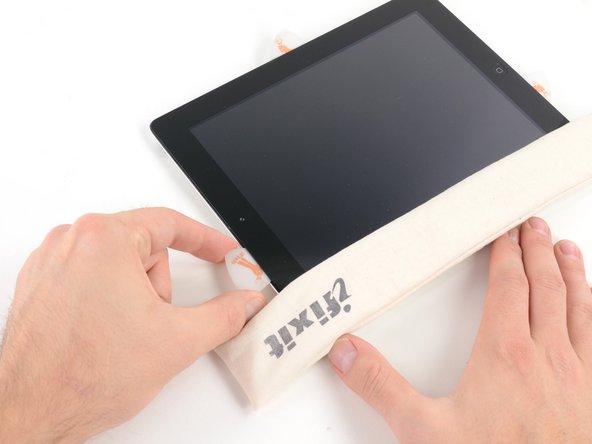
Make sure you place the tool in the proper spot—between the plastic display bezel and the front panel glass.
-
-
Este passo não foi traduzido. Ajude a traduzi-lo
-
Keeping the tip of the plastic opening tool wedged between the front glass and plastic bezel, slide a plastic opening pick in the gap, right next to the plastic opening tool.
-
-
Este passo não foi traduzido. Ajude a traduzi-lo
-
Remove the plastic opening tool from the iPad, and push the opening pick further underneath the front glass to a depth of ~0.5 inches.
-
-
Este passo não foi traduzido. Ajude a traduzi-lo
-
While you work on releasing the adhesive on the right side of the iPad, reheat the iOpener, and replace it on the bottom edge of the iPad.
-
-
Este passo não foi traduzido. Ajude a traduzi-lo
-
While the bottom edge is being heated by the iOpener, begin releasing the adhesive from the right edge of the iPad.
-
Slide the opening pick down along the edge of the iPad, releasing the adhesive as you go.
-
-
Este passo não foi traduzido. Ajude a traduzi-lo
-
If the opening pick gets stuck in the adhesive, "roll" the pick along the side of the iPad, continuing to release the adhesive.
-
-
Este passo não foi traduzido. Ajude a traduzi-lo
-
Before removing the first opening pick from the bottom corner of the iPad, insert a second pick under the right edge of the front glass to keep the adhesive from re-adhering.
-
Re-heat the iOpener, and move it to the top edge of the iPad.
-
-
Este passo não foi traduzido. Ajude a traduzi-lo
-
You will have to release the adhesive securing the antenna to the front panel without damaging the delicate parts attaching the antenna to the bottom of the iPad. Follow the next steps carefully.
-
-
Este passo não foi traduzido. Ajude a traduzi-lo
-
Slide the opening pick around the bottom right corner of the iPad, releasing the adhesive there.
-
-
Este passo não foi traduzido. Ajude a traduzi-lo
-
Slide the tip of the opening pick along the bottom edge of the iPad, releasing the adhesive over the Wi-Fi antenna.
-
-
Este passo não foi traduzido. Ajude a traduzi-lo
-
Once you have moved past the Wi-FI antenna (approximately 3" (75 mm) from the right edge, or right next to the home button) re-insert the opening pick to its full depth.
-
Slide the pick to the right, releasing the adhesive securing the Wi-Fi antenna to the front glass.
-
The antenna is attached to the bottom of the iPad via screws and a cable. This step detaches the antenna from the front panel, ensuring that when you remove the panel, the antenna will not be damaged.
-
-
Este passo não foi traduzido. Ajude a traduzi-lo
-
Continue releasing the adhesive along the bottom of the iPad, pulling the opening pick out far enough to go around the home button, and re-inserting it to a depth of 1/2 inch (10 mm) once the pick is past the home button.
-
-
Este passo não foi traduzido. Ajude a traduzi-lo
-
Continue releasing the adhesive all the way along the bottom edge of the iPad.
-
Leave the opening pick wedged underneath the front glass near the home button.
-
-
Este passo não foi traduzido. Ajude a traduzi-lo
-
Reheat the iOpener in the microwave and set it on the left edge of the iPad to start warming the adhesive in that section.
-
-
Este passo não foi traduzido. Ajude a traduzi-lo
-
Slide the opening pick along the top edge of the iPad, pulling it out slightly to go around the front-facing camera bracket.
-
The adhesive along this section is very thick, and a fair amount of force may be required. Work carefully and slowly, making sure to not slip and damage yourself or your iPad.
-
-
Este passo não foi traduzido. Ajude a traduzi-lo
-
Continue releasing the adhesive along the top edge of the iPad, and slide the opening pick around the top left corner.
-
-
-
Este passo não foi traduzido. Ajude a traduzi-lo
-
Slide the opening pick along the left edge of the iPad, releasing the adhesive as you go. The adhesive is thin here due to the digitizer along the whole left side. Make sure the pick is not too deep (max 1/2 inch) 10 mm to prevent damaging the digitizer.
-
-
Este passo não foi traduzido. Ajude a traduzi-lo
-
Using the opening pick that is still underneath the bottom edge of the iPad, release the adhesive along the bottom left corner.
-
-
Este passo não foi traduzido. Ajude a traduzi-lo
-
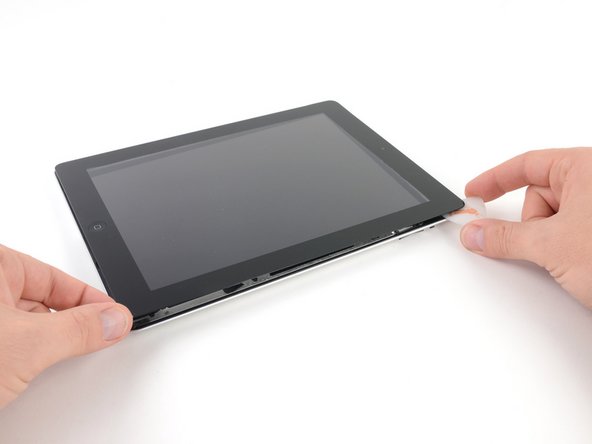
Using one of the opening picks, pry up the bottom right corner of the iPad and grab it with your fingers.
-
-
Este passo não foi traduzido. Ajude a traduzi-lo
-
Holding the iPad by the top and bottom right corners, rotate the front glass away from the iPad.
-
-
Este passo não foi traduzido. Ajude a traduzi-lo
-
Remove the four 2.0 mm Phillips screws securing the LCD to the rear case.
-
-
Este passo não foi traduzido. Ajude a traduzi-lo
-
Lift the LCD from its long edge closest to the volume buttons and gently flip it out of the rear case—like turning the page in a book.
-
Set the LCD face down on the front panel.
-
-
Este passo não foi traduzido. Ajude a traduzi-lo
-
Use the edge of a plastic opening tool to carefully flip up the retaining flaps on the two digitizer ribbon cable ZIF sockets.
-
-
Este passo não foi traduzido. Ajude a traduzi-lo
-
Use the edge of a plastic opening tool to peel the digitizer cable off the shields on the logic board.
-
Carefully pull the digitizer cable off the adhesive securing it to the side of the rear case.
-
-
Este passo não foi traduzido. Ajude a traduzi-lo
-
Pull the digitizer ribbon cable straight out of its two sockets on the logic board.
-
-
Este passo não foi traduzido. Ajude a traduzi-lo
-
Lift the LCD from its long edge farthest from the digitizer cable and gently flip it toward the rear case—like closing a book.
-
While holding the LCD up, gently slide the front panel away from the iPad. Be careful not to snag the digitizer cable on the rear case or LCD.
-
Set the LCD back into the body for safekeeping.
-
-
Este passo não foi traduzido. Ajude a traduzi-lo
-
Lift the LCD from its long edge closest to the volume buttons and gently flip it out of the rear case—like turning the page in a book.
-
Set the LCD face down on a clean surface. You may want to rest it on a soft cloth to prevent scratches.
-
-
Este passo não foi traduzido. Ajude a traduzi-lo
-
Use a plastic opening tool to lift the display data cable lock upwards.
-
Pull the display data cable out of its socket.
-
-
Este passo não foi traduzido. Ajude a traduzi-lo
-
Remove the LCD assembly from the rear panel assembly.
-
-
Este passo não foi traduzido. Ajude a traduzi-lo
-
If present, remove the piece of tape on the dock connector cable with a plastic opening tool.
-
Use the edge of a plastic opening tool to carefully pry the dock connector cable's connector up from its socket on the logic board.
-
Peel the dock connector ribbon cable off the rear panel.
-
-
Este passo não foi traduzido. Ajude a traduzi-lo
-
Pry the speaker cable connector straight up from its socket on the logic board.
-
-
Este passo não foi traduzido. Ajude a traduzi-lo
-
Remove the following screws:
-
Two 2.1 mm Phillips screws securing one of two metal brackets to the rear case.
-
One 2.6 mm Phillips screw securing the logic board to the rear case.
-
Remove the metal bracket from the rear case.
-
-
Este passo não foi traduzido. Ajude a traduzi-lo
-
If present, use tweezers to remove the piece of tape covering the end of the headphone jack/control board cable.
-
-
Este passo não foi traduzido. Ajude a traduzi-lo
-
Use the flat end of a spudger to flip up the retaining flap on the headphone jack/control board cable ZIF socket.
-
-
Este passo não foi traduzido. Ajude a traduzi-lo
-
Slide the tip of a spudger underneath the headphone jack/control board ribbon cable to disconnect it.
-
-
Este passo não foi traduzido. Ajude a traduzi-lo
-
Remove the two 2.1 mm Phillips screws securing the second metal bracket to the rear case near the digitizer cable socket.
-
Remove the metal bracket from the rear case.
-
-
Este passo não foi traduzido. Ajude a traduzi-lo
-
Use the edge of a plastic opening tool to gently pry the logic board up from the adhesive securing it to the rear case.
-
-
Este passo não foi traduzido. Ajude a traduzi-lo
-
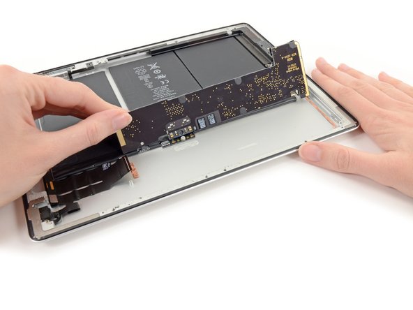
Lift the logic board out from the rear case and flip it over toward the battery.
-
-
Este passo não foi traduzido. Ajude a traduzi-lo
-
Use the tip of a spudger to pry the Wi-Fi antenna connector up from its socket on the logic board.
-
Remove the logic board from the case.
-
-
Este passo não foi traduzido. Ajude a traduzi-lo
-
Reheat the iOpener in the microwave for one minute.
-
Place the heated iOpener on the back of the iPad just right of center (the side opposite the rear facing camera). Let it sit there for 90 seconds to soften the battery adhesive.
-
Move the iOpener to the center of the back of the iPad and let the iOpener sit for another 90 seconds.
-
Move the iOpener to the left edge (the side with the rear facing camera) of the back of the iPad and let the iOpener sit for another 90 seconds.
-
-
Este passo não foi traduzido. Ajude a traduzi-lo
-
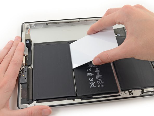
Flip the iPad back over and insert a plastic card between the bottom battery cell and the rear case.
-
-
Este passo não foi traduzido. Ajude a traduzi-lo
-
Starting with the battery cell closest to the dock connector, run a plastic opening tool underneath the edge of the battery closest to the logic board void to make enough room to insert a plastic card.
-
-
Este passo não foi traduzido. Ajude a traduzi-lo
-
Insert the card at the case side corner and slide inward to separate more adhesive.
-
-
Este passo não foi traduzido. Ajude a traduzi-lo
-
Work the card around the corner and insert along the case-side of the cell.
-
Insert the card at as shallow an angle as you can manage to avoid bending the battery.
-
-
Este passo não foi traduzido. Ajude a traduzi-lo
-
Insert the card at the bottom corner (closest to the headphone jack) to free this side of the battery cell.
-
-
Este passo não foi traduzido. Ajude a traduzi-lo
-
Slide the card along the side of the cell to detach any remaining adhesive.
-
-
Este passo não foi traduzido. Ajude a traduzi-lo
-
Gently pry the end of the battery cell away from the case.
-
-
Este passo não foi traduzido. Ajude a traduzi-lo
-
Gently pry the corner of the battery off of the case to begin freeing the final side of the dock side cell.
-
-
Este passo não foi traduzido. Ajude a traduzi-lo
-
Gently pry up the remaining corner of the cell. Avoid bending the cable connecting the battery cells.
-
Leave this card in place to prevent the adhesive from resetting while you loosen the other battery cells.
-
-
Este passo não foi traduzido. Ajude a traduzi-lo
-
On the battery cell nearest the headphone jack, run a second plastic card underneath the edge adjacent to the logic board void.
-
-
Este passo não foi traduzido. Ajude a traduzi-lo
-
Slide the card in to free the corner of the cell from adhesive.
-
-
Este passo não foi traduzido. Ajude a traduzi-lo
-
Pry gently to free the corner of the cell from the case.
-
-
Este passo não foi traduzido. Ajude a traduzi-lo
-
Slide the card under the opposite corner to detach yet more adhesive.
-
-
Este passo não foi traduzido. Ajude a traduzi-lo
-
Give a final swipe to get the last of that stubborn adhesive.
-
-
Este passo não foi traduzido. Ajude a traduzi-lo
-
A final pry, and the card can be left in place to keep the battery propped away from the adhesive.
-
-
Este passo não foi traduzido. Ajude a traduzi-lo
-
Slide the card under the center cell near the cable.
-
Insert the card near the far end of the battery.
-
-
Este passo não foi traduzido. Ajude a traduzi-lo
-
Gently pry the bottom of the cell up from the case.
-
Pry the dock side corner of the cell up from the adhesive.
-
Pry again near the cable to loosen the cell further.
-
-
Este passo não foi traduzido. Ajude a traduzi-lo
-
Slide a corner of the card under the top of the cell (the side adjacent to the logic board void).
-
Use the screw post as a pivot point to detach the last of the adhesive under the battery conector board.
-
-
Este passo não foi traduzido. Ajude a traduzi-lo
-
Insert the cards at the junctures between batteries.
-
Pry upwards to free the battery connector board from the screw post and the battery assembly from the case.
-
-
Este passo não foi traduzido. Ajude a traduzi-lo
-
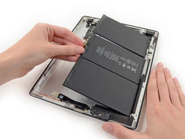
Lift and gently remove the battery assembly from the case.
-


Cancelar: não concluí este guia.
28 outras pessoas executaram este guia.


Um comentário
Nicked (Cut) the Touchscreen cable, Wi-Fi Cable, (Power/ Lock/ Camera) Cable - taking the screen off. All I was trying to do is replace the battery. It was so cheep, I should have purchased items 2 & 3, new screen seam, as spares when attempting the repair to avoid multiple shipping delays. As far as my unbroken screen which I destroyed, I used a razor blade but went in more than 4mm, watch out for that. A difficult time consuming repair. Saying that, without ifixit.com, I would have been paddling up a creek, so special thanks to them for making the repair even possible.