Esta versão pode conter edições incorretas. Mude para o último instantâneo verificado.
O que você precisa
-
Este passo não foi traduzido. Ajude a traduzi-lo
-
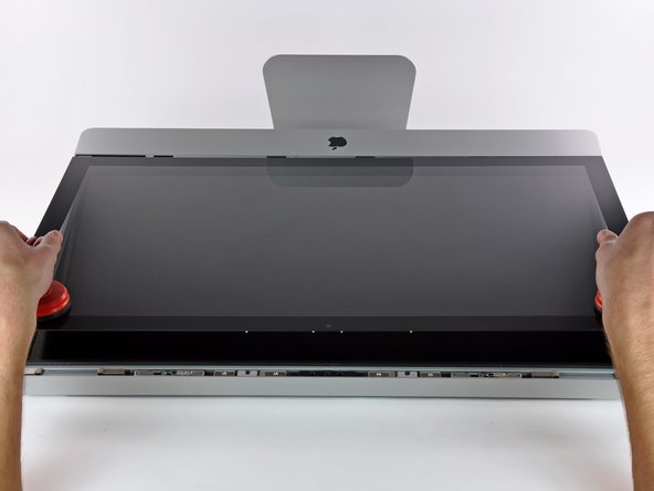
Stick a heavy-duty suction cup near each of the two top corners of the glass panel.
-
While lightly holding the suction cup against the glass, raise the movable handle until it is parallel with the other handle (as indicated by the third picture).
-
-
Este passo não foi traduzido. Ajude a traduzi-lo
-
Gently lift the glass panel perpendicular to the face of the LCD, enough to clear the steel mounting pins attached along the underside of the top edge of the glass panel.
-
Pull the glass panel away from the lower edge of the iMac and carefully set it aside.
-
-
Este passo não foi traduzido. Ajude a traduzi-lo
-
Remove the eight T10 Torx screws securing the LCD to the outer case.
-
-
Este passo não foi traduzido. Ajude a traduzi-lo
-
Carefully lay the iMac stand-side down on a flat surface.
-
Use a thin hooked tool to lift one side of the top edge of the display by its steel outer frame.
-
-
Este passo não foi traduzido. Ajude a traduzi-lo
-
Using your fingers, carefully pull the vertical sync cable out of its socket on the LED driver board near the top left corner of your iMac.
-
-
-
Este passo não foi traduzido. Ajude a traduzi-lo
-
Squeeze the two display data cable connector arms together to unlock it from its socket on the logic board.
-
Pull the display data cable connector away from its socket on the logic board.
-
-
Este passo não foi traduzido. Ajude a traduzi-lo
-
Rotate the display out of the outer case enough to disconnect the LED backlight power cable from the LED driver board.
-
-
Este passo não foi traduzido. Ajude a traduzi-lo
-
Lift the display for enough clearance to disconnect the LCD thermal sensor cable connector from its socket on the logic board.
-
-
Este passo não foi traduzido. Ajude a traduzi-lo
-
Carefully pull the display toward the top edge of your iMac and lift it out of the outer case.
-
-
Este passo não foi traduzido. Ajude a traduzi-lo
-
Remove the four T10 Torx screws securing the optical drive to the outer case.
-
-
Este passo não foi traduzido. Ajude a traduzi-lo
-
Pull the optical drive thermal sensor connector straight away from its socket on the logic board.
-
-
Este passo não foi traduzido. Ajude a traduzi-lo
-
Insert a spudger between the optical drive connector and the optical drive.
-
Twist the spudger to slightly separate the optical drive connector from the optical drive, then use your fingers to pull the connector away from the drive.
-
-
Este passo não foi traduzido. Ajude a traduzi-lo
-
Lift the left edge of the optical drive slightly and pull it away from the right side of the outer case.
-
During reassembly, note that there are two holes in the optical drive face plate into which two stubby plastic posts must engage for proper positioning.
-