Esta versão pode conter edições incorretas. Mude para o último instantâneo verificado.
O que você precisa
-
Este passo não foi traduzido. Ajude a traduzi-lo
-
Before beginning any work on your iMac: Unplug the computer and press and hold the power button for ten seconds to discharge the power supply's capacitors.
-
-
Este passo não foi traduzido. Ajude a traduzi-lo
-
Starting on the left of the display, near the power button, insert the iMac Opening Tool into the gap between the glass panel and the rear enclosure.
-
-
Este passo não foi traduzido. Ajude a traduzi-lo
-
Use the tool like a pizza cutter—roll it along through the gap, and it will cut the foam adhesive through the center.
-
Run the tool up along the left side of the display.
-
-
Este passo não foi traduzido. Ajude a traduzi-lo
-
Continue running the tool up around the top left corner.
-
-
Este passo não foi traduzido. Ajude a traduzi-lo
-
Cut the adhesive along the top left of the display.
-
-
Este passo não foi traduzido. Ajude a traduzi-lo
-
Push the tool around the top right corner of the display.
-
-
Este passo não foi traduzido. Ajude a traduzi-lo
-
Wheel the tool down along the right side of the display.
-
-
Este passo não foi traduzido. Ajude a traduzi-lo
-
Finish pushing the opening tool to the bottom of the right side of the display.
-
-
Este passo não foi traduzido. Ajude a traduzi-lo
-
Starting from the top right corner of the iMac, wedge a plastic card between the display and frame.
-
-
Este passo não foi traduzido. Ajude a traduzi-lo
-
Gently twist the plastic card sideways to create a gap between the display and frame.
-
Move slowly and be careful not to stress the display glass too much—you only need to make a gap of about 1/4".
-
-
Este passo não foi traduzido. Ajude a traduzi-lo
-
Slide the card toward the center of the display to cut any of the remaining adhesive along the top right corner of the iMac.
-
-
Este passo não foi traduzido. Ajude a traduzi-lo
-
Wedge the plastic card into the top right corner once again, and leave it there to prevent the adhesive from resticking.
-
-
Este passo não foi traduzido. Ajude a traduzi-lo
-
Insert a second plastic card into the gap between the display and frame near the top left corner of the iMac.
-
-
Este passo não foi traduzido. Ajude a traduzi-lo
-
Gently twist the card upward, slightly increasing the space between the display and frame.
-
-
Este passo não foi traduzido. Ajude a traduzi-lo
-
Slide the plastic card toward the center, again stopping just before the iSight camera.
-
-
Este passo não foi traduzido. Ajude a traduzi-lo
-
Wedge the plastic card back into the top left corner.
-
-
Este passo não foi traduzido. Ajude a traduzi-lo
-
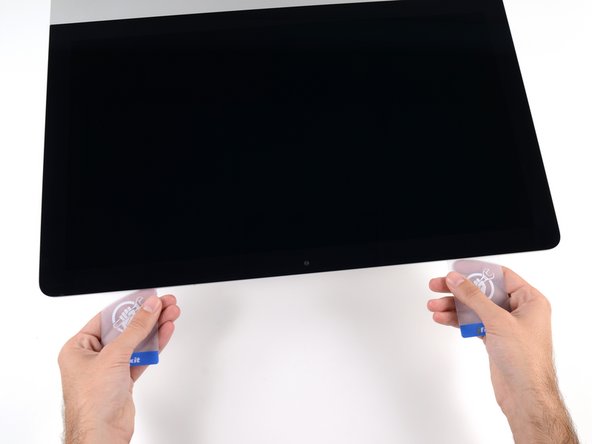
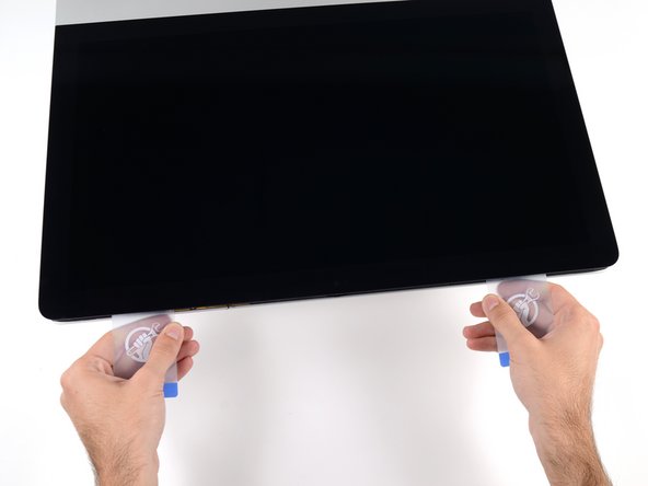
With both plastic cards inserted as shown near the corners, gently twist the cards sideways to increase the gap between display and case.
-
Begin to lift the top of the display up from the frame.
-
-
Este passo não foi traduzido. Ajude a traduzi-lo
-
Hold the display with one hand while using your other hand to unplug the display power cable.
-
-
Este passo não foi traduzido. Ajude a traduzi-lo
-
Continuing to support the display with one hand, flip up the metal retaining bracket on the display data cable.
-
Carefully pull the display data cable from its socket on the logic board.
-
-
Este passo não foi traduzido. Ajude a traduzi-lo
-
Grasp the small tab at the end of one of the bottom edge display adhesive strips and pull the adhesive toward the top of the iMac to remove it.
-
Repeat this step with the other adhesive strip and remove it.
-
-
-
Este passo não foi traduzido. Ajude a traduzi-lo
-
Lift the display up from the frame and remove it from the iMac.
-
It may be necessary to slowly lift from one side to peel against the remaining adhesive.
-
-
Este passo não foi traduzido. Ajude a traduzi-lo
-
Remove the following five Phillips screws holding the lower support bracket in place:
-
Four 3.2 mm screws
-
One 1.7 mm screw
-
-
Este passo não foi traduzido. Ajude a traduzi-lo
-
Remove the lower support bracket from the iMac enclosure.
-
-
Este passo não foi traduzido. Ajude a traduzi-lo
-
Gently pull the right speaker cable connector straight down and out of its socket on the logic board.
-
-
Este passo não foi traduzido. Ajude a traduzi-lo
-
Remove the two 10 mm T10 Torx screws securing the right speaker to the rear enclosure.
-
-
Este passo não foi traduzido. Ajude a traduzi-lo
-
Insert the tip of a spudger between the right speaker and the antenna cable, running it down the right side of the speaker to de-route the cable from its channel.
-
-
Este passo não foi traduzido. Ajude a traduzi-lo
-
Tip the right speaker forward out of the rear enclosure, about 1 cm.
-
Pull the speaker straight up and remove it from the iMac.
-
-
Este passo não foi traduzido. Ajude a traduzi-lo
-
Remove the following T10 Torx screws securing the hard drive brackets to the iMac:
-
Two 21 mm screws
-
One 9 mm screw
-
One 27 mm screw
-
-
Este passo não foi traduzido. Ajude a traduzi-lo
-
Remove the left and right hard drive brackets from the iMac.
-
-
Este passo não foi traduzido. Ajude a traduzi-lo
-
Use the tip of a spudger to push each side of the power button cable connector and gently walk it out of its socket.
-
-
Este passo não foi traduzido. Ajude a traduzi-lo
-
Use the tip of a spudger to push each side of the power supply control cable connector and gently walk it out of its socket.
-
-
Este passo não foi traduzido. Ajude a traduzi-lo
-
Remove the two 7.2 mm T10 Torx screws securing the power supply to the rear enclosure.
-
-
Este passo não foi traduzido. Ajude a traduzi-lo
-
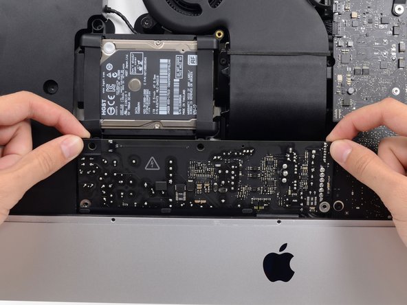
Pull the power supply slightly up and out from the rear enclosure.
-
Rotate the power supply counterclockwise, lifting the right side up about an inch higher than the left.
-
-
Este passo não foi traduzido. Ajude a traduzi-lo
-
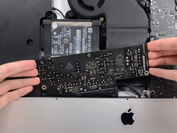
Slide the power supply to the right to clear the screw posts on the rear enclosure.
-
-
Este passo não foi traduzido. Ajude a traduzi-lo
-
Rock the power supply forward and remove it from its recess in the rear enclosure.
-
-
Este passo não foi traduzido. Ajude a traduzi-lo
-
Squeeze the tab on the back side of the DC power cable connector and pull it straight out of its socket on the back of the logic board.
-
-
Este passo não foi traduzido. Ajude a traduzi-lo
-
Use the flat end of a spudger to press the clip on the side of the AC inlet cable connector inward.
-
While pressing on the release clip with the spudger, grasp the AC inlet cable, and pull the connector straight out of its socket.
-
-
Este passo não foi traduzido. Ajude a traduzi-lo
-
Gently pull the fan cable connector straight out of its socket on the logic board.
-
-
Este passo não foi traduzido. Ajude a traduzi-lo
-
Remove the three 10 mm T10 Torx screws securing the fan to the rear enclosure.
-
-
Este passo não foi traduzido. Ajude a traduzi-lo
-
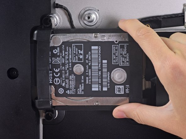
Lift the hard drive from the edge nearest the logic board and pull it slightly out of its recess.
-
-
Este passo não foi traduzido. Ajude a traduzi-lo
-
Use a spudger to disconnect the single SATA power and data combo cable by gently prying its large plastic connector away from the hard drive.
-
-
Este passo não foi traduzido. Ajude a traduzi-lo
-
Remove the 7.3 mm T8 Torx screw securing the hard drive tray to the rear enclosure.
-
-
Este passo não foi traduzido. Ajude a traduzi-lo
-
Gently pull the left speaker cable straight out of its socket on the logic board.
-
-
Este passo não foi traduzido. Ajude a traduzi-lo
-
De-route the left speaker cable by pulling it straight up out of the retaining clip in the back of the rear enclosure.
-
-
Este passo não foi traduzido. Ajude a traduzi-lo
-
Similarly to the previous step, de-route the SATA and power cables by pulling the braid straight up out of the retaining clip.
-
-
Este passo não foi traduzido. Ajude a traduzi-lo
-
Peel up the piece of tape connecting the left speaker connector to the SATA power and data cables.
-
-
Este passo não foi traduzido. Ajude a traduzi-lo
-
Flip up the metal retaining bracket on the FaceTime camera cable connector.
-
Pull the FaceTime camera cable straight out of its socket on the logic board.
-
-
Este passo não foi traduzido. Ajude a traduzi-lo
-
Remove the two 4.0 mm T5 Torx screws securing the four antenna connectors to the AirPort/Bluetooth card.
-
-
Este passo não foi traduzido. Ajude a traduzi-lo
-
Disconnect all four antenna connectors by prying them straight up from their sockets on the AirPort/Bluetooth card.
-
-
Este passo não foi traduzido. Ajude a traduzi-lo
-
Use the flat edge of a spudger to pry the headphone jack cable connector from its socket on the logic board.
-
-
Este passo não foi traduzido. Ajude a traduzi-lo
-
Remove the following T8 Torx screws securing the exhaust duct to the rear enclosure:
-
Two 6.2 mm screws
-
Two 4.7 mm screws
-
-
Este passo não foi traduzido. Ajude a traduzi-lo
-
Remove the four 7.3 mm T8 Torx screws securing the logic board to the rear enclosure.
-
-
Este passo não foi traduzido. Ajude a traduzi-lo
-
Tilt the top of the logic board away from the rear enclosure.
-
-
Este passo não foi traduzido. Ajude a traduzi-lo
-
Lift the logic board straight up and out of the iMac.
-
-
Este passo não foi traduzido. Ajude a traduzi-lo
-
You can use a USB flash drive and/or ethernet cable to ensure the logic board is seated correctly while you screw it in.
-
-
Este passo não foi traduzido. Ajude a traduzi-lo
-
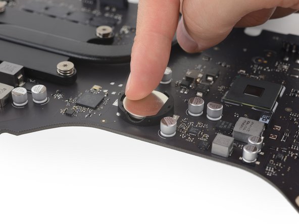
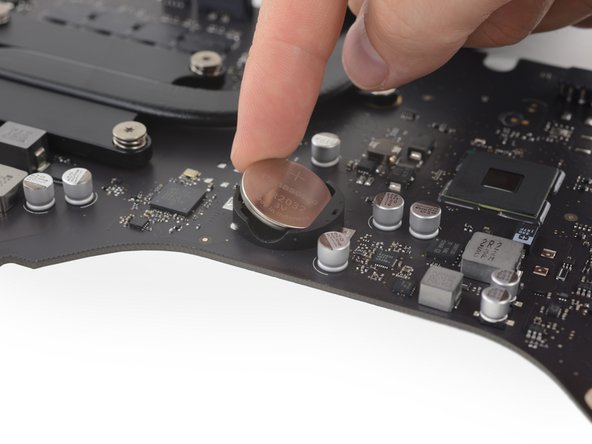
Gently push the battery away from the two plastic nubs. (This puts increased pressure on the spring contact at the other end.)
-
Once the battery's edge clears the two nubs, tilt it up out of its socket.
-


Cancelar: não concluí este guia.
3 outras pessoas executaram este guia.

3 comentários
Hmm. I don't see a single place in these instruction, including the parts needed list, that tells which battery is required. From one of the photos it looks like BR2032.
As I needed to replace the failing hard drive in my late 2015 21.5" iMac anyway, and the iMac is now nearly 8 years old, I figured I may as well replace the PRAM battery as well since I've got the screen off. The battery must be getting near its end of life anyway, right? And I don't want to have to open this iMac up again anytime soon. And there seems to be no way to tell what its voltage is without taking it out. So after going through this whole process and putting in a new battery (which registered 3.40 volts at installation), I measured the voltage of the old, original battery. 3.19 volts. I guess I could have waited another 8 years at this rate before replacing it! So if this helps anyone - as long as you keep your iMac plugged in, the PRAM battery in these models might last a good 16 years I guess. (I really wish that if they could not provide a way to measure the remaining life span or at least the voltage of the battery, they would have put it on the other side of the logic board!)
By the way, regarding BR2032 vs CR2032: Apple used BR2032 for the PRAM battery on these and many other iMac models, but the BR2032 is much more difficult to get hold of than the CR2032, as well as more expensive. (It's supposed to hold up better under the heat of the environment it's in.) However, I recently had to open a 2009 iMac again, two years after doing some prior work on it: beside the other work I had put in a CR2032 back then. The CR2032 I removed still had 3.14 volts after two full years in the 2009 iMac. So I don't think the CR2032 would hold up as long as a BR2032, but at that rate I suppose it would get at least 4 years of service before dropping too low.