Introdução
This guide details removing the logic board in a 2017 iMac 4K in order to upgrade the RAM and the SATA hard drive (for example, if you purchased the Max Your Mac kit).
Some images in this guide were taken from the 2015 model, which has some small visual differences.
If you are replacing/upgrading your hard drive, be sure to clone your existing hard drive onto the replacement drive prior to performing this upgrade to keep your files and operating system in place.
This guide is marked "potentially dangerous" because it requires you to handle a power supply that contains large capacitors. Unplug the iMac and hold the power button down for at least 10 seconds to help discharge the capacitors. Handle the board by the edges and do not touch surface components.
O que você precisa
-
-
Before beginning any work on your iMac: Unplug the computer and press and hold the power button for ten seconds to discharge the power supply's capacitors.
-
-
-
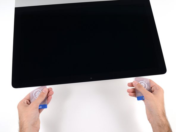
Starting on the left of the display, near the power button, insert the iMac Opening Tool into the gap between the glass panel and the rear enclosure.
Don’t get too worried about starting exactly where the picture says. The glue is stronger in some parts so just start wherever is easier and then work slowly and patiently around in the direction shown.
As this guide doesn’t cover replacing the adhesive strips, I found referring to the following was useful (noting that it’s not for the same model of iMac, so the modification they mention wasn’t necessary): iMac Intel 21.5" EMC 2544 Adhesive Strips Replacement
This part of the exercise should be done with extreme patience. I took my sweet time with the opening tool, rolling it through the entire panel and enclosure gap over and over again, until I was very sure no parts were sticking together anymore. And when I thought I was I done, I decided to do it over again.
You can "warm up" the adhesive before try to cut it with the tool using a hair dryer. Heat the edges for about a minute, keep moving it so you don't cause stress in the glass. Also the above note.. use the tool and then the cards. Do not use a guitar pick or other objects as the thickness will cause you to break the front glass, which is a bonded part of the display (expensive).
Merci pour ce conseil
-
-
-
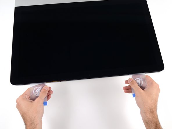
Use the tool like a pizza cutter—roll it along through the gap, and it will cut the foam adhesive through the center.
-
Run the tool up along the left side of the display.
If re-opening a screen that was opened and re-attached using iFixit’s adhesive strips, I would strongly recommend heating it first with an iOpener, heat gun or hair dryer. 20 minutes after attaching with the iFixit adhesive I tried to open it again with the pizza slicer to fix something and cracked the screen on the left-hand side.
-
-
-
Continue along the top of the display.
In this step can I cut along the display without make any damage to the front camera?
Hi! Actually - there is no need to cut the tape around the camera area - there is no tape to cut at all! And so, the way go is easy - just pass 10 mm to the left and to the right from camera and start cutting!
P.S. Just did the whole procedure to replace a RAM and to add SSD on PSIe an hour ago! Seems to be different reading the instructions... you know - 2/10 and so on. But it's really not that hard, trust me. I'll give it 5/10.
P.P.S. By the way there is one trick to pass the difficult steps. Any action which requires pulling smth (motherboard, speaker, power supply unit) from the narrow crack (or should i say - slit?) at the bottom of your Imac is really not so easy.
And the trick is to first remove a thin metal stripe with some kind of insulation on it which held by 5 small (very small!!) screws at the bottom of your Imac. After you done it - it's easy to pull everything! Pay attention to the fact that one of this 5 screws at the center are more shortly than others.
If you're changing cracked EMC 2638 display to new assembly, there's two more steps:
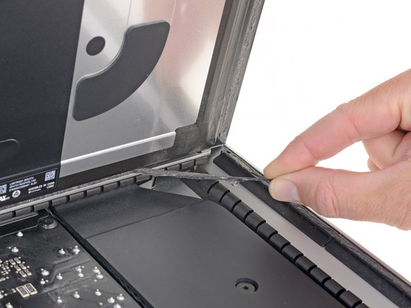
Step 24: Use the tip of a spudger to flip up the metal retaining bracket on the display data cable.
Carefully pull the display data cable from its socket on the display assembly.
Step 25: Use the tip of a spudger to unplug bracket of the thermal sensor small cable near display data cable.
Carefully remove scotch tape covering thermal sensor. Using iSesamo or flat tip of the spudger carefully peel the thermal sensor away.
omg - forgot to switch the termal sensor from the old display...
now fan runs like crazy...
-
-
-
Finish pushing the opening tool to the bottom of the right side of the display.
Yes, do it many times to loosen the adhesive.
Would be good data to show the 3 areas (wifi antennas where the "tape" is larger and covers them. The rest of the "tape" is 1.4" and easy. Also after removing the display, be sure to remove the old "tape" from both the display and the rubber parts of the case. Use the spudger to start an end and it should pull off easily. Careful on the baackside of the display as you can scratch off the black paint/covering.
-
-
-
Starting from the top right corner of the iMac, wedge a plastic card between the display and frame.
this step is extremely important NOT to stick in the cards too far….. doing so, you risk a 600 euro replacement as I experienced………
I drew a 3/8” line on my cards with a marker first.
I’m reading this on the EU store, please change all measurements to cm/mm.
@ifixit The next batch of cards you create should have a line printed on the card 3/8” in from the edges. Would make a nice reference.
Better to remove stand wedge at this point? Can’t see from pics
-
-
-
Gently twist the plastic card sideways to create a gap between the display and frame.
-
Move slowly and be careful not to stress the display glass too much—you only need to make a gap of about 1/4".
This part must be done very carefully or you can damage the flat cable from display, despite it was under a iron cover.
-
-
-
Slide the card toward the center of the display to cut any of the remaining adhesive along the top right corner of the iMac.
-
-
-
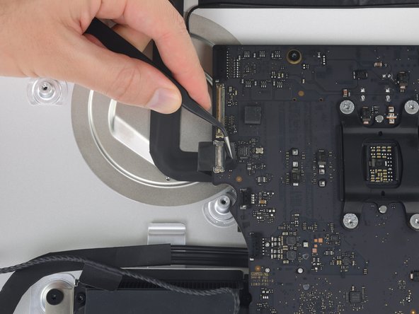
Hold the display with one hand while using your other hand to unplug the display power cable.
Can this cable be replaced? I am worried mine is damaged. I have no display after the screen fell and stressed the display flex cables following an SSD upgrade.
This step should be done with extreme caution and care, as this step 19 is not described in great detail (sorry, author).
The first (most outward) cable will slide out by gently pulling it by its tabs. The second (inner) cable is more tricky, as the locking lever must be moved backward first, before gently pulling backward on the cable connector. The angled tweezers are useful here, to help lift that locking lever, because fingers are too big for this.
I found the best way to unplug this display power cable was to use my right hand, and the fingernails of my index finger and thumb to grab the ends of the tabs on either side of the connector, squeeze, and pull the connector out gently.
i think the cable nearest the case edge is held in by friction and can be gently pulled, maybe with fingernails or a spudger. The next cable is held by a wire lever clip as described above it unlocks so the cable can be removed. These cables are also fiddly to re-insert, I didn't get one of them home and had no display after power-up, so at the end, don't re-seal the screen until tested.
-
-
-
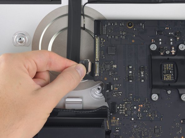
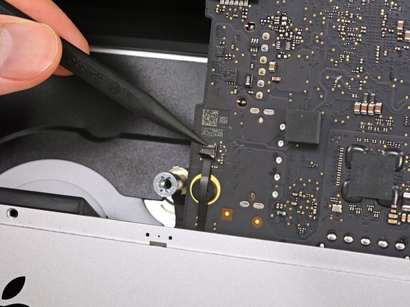
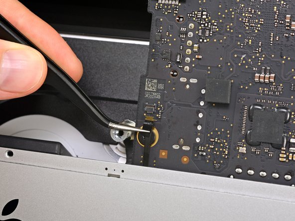
Continuing to support the display with one hand, flip up the metal retaining bracket on the display data cable.
-
Carefully pull the display data cable from its socket on the logic board.
Cannot seem to find a replacement cable for this, as I suspect mine is damaged. Can’t even find a part number. Anyone know what it might be?
https://www.amazon.com/gp/product/B08TTL...
That's the part I ordered for mine and it seems to work ok. I did make a point of contacting the seller and advising them of my requirement and they ensured I got the right part and it matches the description of the link. Bear in mind I bear no responsibility if yours does not work since I am just sharing what I did and what I ordered. Thanks.
I also need that cable.
It's a little difficult to tell... but looking at the connection to the logic board on the video data cable, are the pins faced up or down?
On the display, same question since it appears you have to "twist" the cable during the reconnection step.
For this particular cable, take a good look before pulling on anything. Plug is locked on its socket with a bracket. You can lift this bracket by holding the small, flat black plastic handle that is attached to it. If you're struggling to grab it, use the end of the pizza roller handle to lift it, or the tweezers. Cable then comes off by pulling parallel to the main board.
How can I tell if either of this cable is bad? My iMac display won't turn on after reconnecting it. I'm using an external display and everything is working except for the iMac display. If I go to settings - display the built-in display is recognize. But again nothing shows up in the screen - not even the apple logo when turning it on.
-
-
-
Lift the display up to a near-vertical position.
The best way to remove the chin adhesive is to use the tabs at either end (there are two strips that run from each outside corner to near the centre). Carefully pull the tabs up and the strips should peel off.
-
-
-
Grasp the small tab at the end of one of the bottom edge display adhesive strips and pull the adhesive toward the top of the iMac to remove it.
-
Repeat this step with the other adhesive strip and remove it.
At step 21-22, releasing the adhesive strips from the bottom of the display, I noticed a tab on the outer end of each strip. Pull the tab to remove the whole strip, no need to mess around with the plastic cards!
Instead of the plastic cards, use the flat end of a spudger. Use it as scraper. Be careful as there are antennas mounted on the inside edge of the frame on the right side (facing you), and the top right (facing you). The original adhesive strips are on those as well. - ECJ
A little bit of hot air (eg. hair dryer) will help soften the adhesive. Use a piece of cardboard or equivalent if you want to avoid blowing hot air towards the electronics.
Be careful to remove absolutely everything - any remainder will create a bump and prevent your screen from sticking back to the frame when reassembling.
-
-
-
-
Lift the display up from the frame and remove it from the iMac.
-
It may be necessary to slowly lift from one side to peel against the remaining adhesive.
Après l'étape 23, j'ai suivi les instructions de la vidéo intitulée: Upgrade RAM in a mid-2017 21-inch iMac without complete disassembly.
Lien: https://www.youtube.com/watch?v=_k9I7N9B...
J'ai pu upgrader la RAM en enlevant juste le ventilateur.
-
-
-
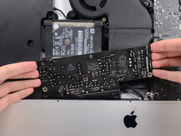
Remove the following five Phillips screws holding the lower support bracket in place:
-
Four 3.2 mm screws
-
One 1.7 mm screw
2 notes for reassembly, carful with screws not to strip the heads as they are really really small, make note to cut a gap in the the adhesive over the whole for the microphone.
I managed to strip the head of one of the screws when putting it back in. So be carful with them when putting in / taking out. If you strip it on the way out you will need to take a fine drill and rill it out. Going back in, well as long as you never need to strip it down again not a problem.
The second problem is a real pain, you need to make sure to cut a gap in the adhesive just to the right of Center at the button to allow for the microphone opening. If you don’t, the adhesive tape will stop any real pick up on the Mic, so you just need to cut a small gap in it before putting on the screen. Unfortunately I didn’t find this out (or do my checked before sticking it all back down, so have to pull screen back off and reapply new adhesive
witha cut out in it at an other time.Refer her for more info on the mic / adhesive work around —> Muffled Microphone - iMac 21.5" (mid 2017) - Following Adhesive Strips
-
-
-
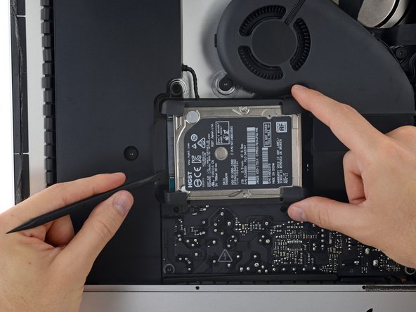
Remove the following T10 Torx screws securing the hard drive brackets to the iMac:
-
Two 21 mm screws
-
One 9 mm screw
-
One 27 mm screw
At step 26, when reassembling, it's super easy to over-tighten the 9mm screw and strip the brass ferrule out of its hole in the plastic bracket (%#*@).
Mine has 4 different length screws, the two red colored 21mm screws in this guide are actually two differ lengths
buongiorno, l'imac del 2019, non monta alcuna ssd, ma monta una m2 direttamente sulla scheda madre!
pertanto nella guida andrebbe aggiunto il cavo sata con sensore temperatura da aggiungere sulla scheda madre, per poter collegare un nuovo hd ssd altrimenti rimarrete come me bloccati con un imac aperto e non assemblato, in attesa di ricevere il cavo acquistato su internet da amazon o terze parti.
vi consiglio inoltre di aggiungere una foto reale del ò'imac 2019 nella guida in cui manca l'ssd, renderà subito la problematica che avranno in molti!
Hi, mine doesn’t HAVE an HD/SSD to remove, the bay is empty (yes it was fully working yesterday. So what do we do ? I see someone else with the sane issue above….
-
-
-
Use the tip of a spudger to push each side of the power button cable connector and gently walk it out of its socket.
I would advise that before removing the PSU unit and all other components from the bottom of the case that you remove the 5 screws at the bottom of the display which hold an insulation strip in place.
The guide shows this piece removed, but does not tell you how to remove it.
There will be 5, small J1000 screws. The middle one, which goes over Apple Logo is the shorter one of the 5, all others are the same length. Once this piece is gone removing the components is much easier, and chance of damage lessened.
Added to the guide. Thanks for the tip!
No need to remove power board and logic board and all other components, just remove the fan and it is quite "easily" accessable to change the RAM. Just need to use the tools to remove the old RAM and carefully install the new RAM.
I just did it without removing the logic or power board
could you elaborate a little more, I would love to skip the rest of these steps. How did you accomplish this?
ej P -
Oleksandr Trokhymchuk,
Thank you! You just saved me so much time! I wouldn’t call this “easy” but it saved me a lot of time and effort.
ej P: remove the fan assembly first. Then remove the connector that runs from the iSight camera to the logic board on the left.
the RAM is located right near that cable. It’s tricky to remove but you can pop open the connectors with a black nylon stick and the RAM chip will pop up at 45 degrees. Make a mental note on which way you will need to install the new ram as it’s tough to see. For the Crucial memory I got it was label side facing away you (facing towards rear metal enclosure).
the second chip has a plastic adhesive piece on it that you should probably attach to the new ram.
remove both chips then install the new ram in sequence from the board out.
In the photo for Step 28, the power button cable connector is placed around the power board screw hole on the top left of the power board.
However, on the iMac I upgraded, the power button cable connector was “fed” through the power power screw hole on the top left of the power board. The cable was too short to run around and below the hole.
Hence, I had to ensure the cable was “fed” through the hole during re-assembly and the screw carefully screwed back through the hole.
I guess every iMac is assembly just a bit differently, just to make repairs that much more fun.
This is not correct and may have been assembled incorrectly during a previous repair.
Just replaced the hard drive and RAM with SSD and 16GB respectively and did NOT remove the power supply or logic board. Tricky is a word to describe putting the RAM in without removing the logic board. You work in the dark with little room to get your fingers in between the logic board and the back of the case. I put the first RAM chip in without a problem (the one next to the logic board), but the second to four tries and dropped it behind the logic board three times before finally getting it to position correctly. Just impossible to see and must work but feel. Still it was faster than removing all the components… though did remove the fan (needed cleaning anyway). All in all I can’t say enough about the help the guide was through the upgrade ! Thanks !
I found this connector to be very tight and was afraid of breaking it off. I just kept slowly working on it—it did eventually come out.
I did try to sneak the RAM in without removing the logic board but my fingers were too big. I found it too difficult and just continued on with this guide.
I was not able to install the memory without removing all the components. My fingers are too big and I could barely get in that tight spot to swap out the memory. The hardest part about the power supply is that one connector under the chin next to the Apple logo. Once it is out, you are home free because it is so easy to plug it back in when you are putting it all back together again. Ridiculous that Apple did not put a simple access door behind those memory slots because they are on the backside of the Mac! They did an access door on the PowerBooks and it did not ruin the appearance. They could have designed a cool looking pop out door that only had a thin seam around it so it would still look good. Then you could remove the access door to upgrade the memory easily.
Does anyone know if this is the same situation as in the 2017 model? I just changed RAM in the 2017 version and also skipped taking out the logic board. I just bent a pair of tweezers and put some tape around the tips to make them less scratchy and used them to place the RAM modules into the slots. Worked supereasy and much much quicker than performing the complete tear down of the whole machine.
This step is impossible!
@wizdomonwheels, I don’t see how I can get the RAM shield off of the logic board to access the RAM without removing the logic board. What am I missing?? I’m guessing that those of you that are suggesting this technique are working on older iMac models that don’t have the RAM shield.
Yes, you are correct. It is likely the various steps are a bit different on each model. If I recall I was likely working on a 2015 or older system. If there’s a shield in the way, I can’t think of a way you could get around it without pulling the logic board.
-
-
-
Remove the two 7.2 mm T10 Torx screws securing the power supply to the rear enclosure.
In my case, the left side corner of the PS was caught against the Lower Support Bracket, and I had to remove the LSB in order to get the PS freed and out.
I think the author Walter Galan should put this in the main section of his instructions. I have TWO identical iMac 14,1 / i5 2.7GHz / 21 Inch Late 2013 / Order ME086LL/A. They both required removing the LSB. Thank you very much Walter Galan & others for your contributions.
Those screws were definitely not T10 but T9 on my unit
Those screws were T8 on my unit.
c'est du torx 08
-
-
-
Tilt the power supply forward.
When replacing the PSU (on the re-build) take care not to trap the power button cable behind it - I did...
-
-
-
Pull the power supply slightly up and out from the rear enclosure.
-
Rotate the power supply counterclockwise, lifting the right side up about an inch higher than the left.
In my case, the left side corner of the PS was caught against the Lower Support Bracket, and I had to remove the LSB in order to get the PS freed and out.
I think the author Walter Galan should put this in the main section of his instructions. I have TWO identical iMac 14,1 / i5 2.7GHz / 21 Inch Late 2013 / Order ME086LL/A. They both required removing the LSB. Thank you very much Walter Galan & others for your contributions.
-
-
-
Squeeze the tab on the back side of the DC power cable connector and pull it straight out of its socket on the back of the logic board.
when pulled the cable, even slightly, the actual female piece that connects to the logic board came off. am i screwed?
Repairing sockets that come off the logic board is possible, but very specialised work. Unless you have a magnifying lamp and the necessary desoldering and soldering skills, it will be difficult but not impossible.
I could not disconnect this cable without fear of breaking something (as previous posters did). I found that I could skip this and the next step by wrapping the power supply in a couple layers of a small towel (to prevent shorting with any other metal surfaces), and laying the power supply on the aluminum face of the iMac near the Apple logo. This got it out of the way enough to do what I needed on the logic board (changing PRAM battery) after completing removal of the other items in this guide.
-
-
-
Use the flat end of a spudger to press the clip on the side of the AC inlet cable connector inward.
-
While pressing on the release clip with the spudger, grasp the AC inlet cable, and pull the connector straight out of its socket.
I didn't disconnect the input cable to the power supply. Because I had the machine lying on its back throughout, I placed it on to the metal bit at the bottom of the machine instead (with a cloth to stop the metal getting scratched). The AC inlet cable was pretty tricky to get un-locked, and the PSU sat on the case fine. It didn't hinder anything else throughout the guide.
I thought from Dave’s comment that I could leave the power supply completely in place, but I was mistaken. In order to remove the hard drive assembly after you remove the center screw in it, you’ll need to at least unscrew it and the HD assembly will slip out. Like Dave said, you don’t need to unplug the AC or PSU, which I left hanging.
Getting power supply to the logic board unplugged is also tricky without unscrewing the two bottom screws. They didn’t make this part easy.
I would like to thanks Dave Hallett for his tip of not removing the AC inlet connector of the power supply. I simply wrapped the board in bubble wrap and taped to the iMac case, out of the way, thus giving access to the remaining disconnection procedures and preventing the board from scratching to the iMac case. It also made reassembly much simpler.
Yeah, that AC inlet plug was a nasty one to unplug, mainly because I was trying not to bump the solder joints on the PSU. After a few wiggles and pulls while manipulating the spudger tool to release the clip, it finally unplugged. Made it easier by removing the PSU completely so you don’t have to worry about it. Don’t worry, plugging it back in is a breeze!
With the right tool this plug comes out very easily. Forget about your tiny computer tools, go to the garage and grab a regular old needle nose pliers. Grab the clip and the plug at the same time. The plug will come right out.
Carin Ann— The most helpful comment on this procedure. After reading what you wrote I maneuvered the board, grabbed the clip with my left hand (a little awkward because of the cooling enclosure), squeezed the front of the plug, and got it out.
-
-
-
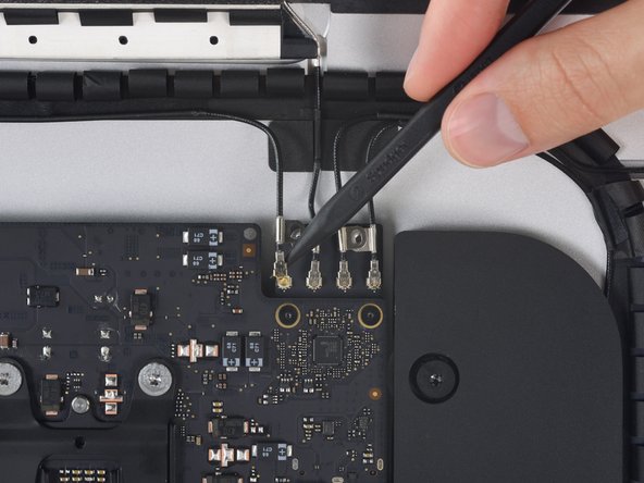
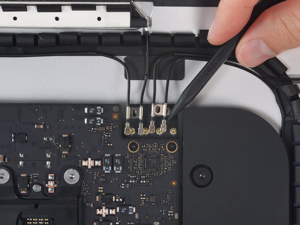
Gently pull the fan cable connector straight away from its socket on the logic board.
-
-
-
Remove the three 10 mm T10 Torx screws securing the fan to the rear enclosure.
In this photo the hard drive brackets and tray are fully assembled. But, you’ve just dismantled about half of it already in early steps. This photo is apt to confuse you a bit when you’re doing everything in reverse order.
Another way to say what Tim said above:
For reassembly, this picture, showing the hard drive brackets back in place, is misleading. Leave them off still.
IF, at this stage, you reinstall the hard drive brackets, when you get to the time to reinstall the power supply, you will have to backtrack and take the brackets off.
-
-
-
Remove the fan from the iMac.
For reassembly, this picture, showing the hard drive brackets back in place, is misleading. Leave them off still.
IF, at this stage, you reinstall the hard drive brackets, when you get to the time to reinstall the power supply, you will have to backtrack and take the brackets off.
-
-
-
Lift the hard drive from the edge nearest the logic board and pull it slightly out of its recess.
-
-
-
Use a spudger to disconnect the single SATA cable by prying it gently away from the hard drive.
-
Remove the hard drive assembly from the iMac.
Not only is it useful to loosen up the speaker next to the SATA connector I found it helpful to use a pen to mark the exact location of the edges of the SATA connector on top of the new drive, so I could guide the connector in place. It also helps to put the bumpers in after you get this SATA connector in place.
Waiting to put the bumpers on until after the SATA cable is attached was a must! Also loosing the speaker and moving over a couple centimeters was a huge help. Thanks
-
-
-
Peel the rubber bumper off one side of the hard drive.
-
Repeat for the other side.
reconnecting the new drive can be a little tricky as the sata connector in the Mac is hard to align. I found that it helps to move the end of the bumpers out of the way, then push them back into position once the drive is connected.
Thank you for the tip!
Can I install a Samsung 850 EVO 500GB to replace my 1TB 5400rpm disk? and is a seperate thermal sensor/cable needed to prohibit the fan to run at 100% all the time?
Yes you can install ANY SATA SSD.
And no … there is no thermal sensor on the drive. You don’t need them on these models.
Can I install a Seagate FireCuda 2TB to replace my 1TB 5400rpm disk? and is a seperate thermal sensor/cable needed to prohibit the fan to run at 100% all the time?
Did you ever find out if you could replace your 500 GB with that Firecuda? I’m looking at doing that. I need more storage for my 500 GB photos library and don’t want to pay so a ton for the SSD that is big enough.
The SSD was a HUGE performance boost over the 5400rpm drive my iMac came with. If you’re pulling your hair out because Lightroom has become excruciatingly slow, upgrade your hard drive to SSD. You will not be disappointed.
The kit has everything you need. Follow these instructions carefully and you’ll be fine.
Huge improvement! It’s like a new machine. Highly recommended upgrade.
Take care with the adhesive strips, and don’t forget to set new SSD as the boot disk (System Preferences, Startup Disk) after you’ve tested its bootable.
I previously had a fusion drive and installed a SSD. Will there be any issues with the ssd portion of the fusion drive? I still see it there in disc utility. Also, I’m showing two SSDs, along with the 32 gig one. Is that correct or did I create something that shouldn’t be there?
I have this same question. I’m showing 2 drives but 1 is grayed out on the computer screen when I click on it nothing happens.
Frank -
A fusion drive combines two physical disks via software to act as one. It it something that has to be done manually and expressly. When you first got the computer, your fusion drive combined disks A (SSD) and B (HDD). If you replaced B, then you probably have an unused 32 GB blade SSD along with your new SSD. It possible to create another Fusion drive, but you’d have to start from zero, because creating a fusion drive erases the individual disks completely.
also, not 100%, but I tried for several hours the other day and I’ve come to the conclusion that my version of Big Sur (11.1) doesn’t support Fusion Drives. Correct me if I’m wrong. Or maybe it’s because I’m running Big Sur on an unsupported iMac.
David -
The hardest part was to plug the connector into the new SSD. I loose the two screws of the adjacent (left) speaker and move it just enough to have sufficient space to introduce my fingers to push the conector into the SSD. Left the replace of the rubber bumpers after reconnect the SSD, is easy to handle without it.
I bought Samsung QVO 1TB SSD and now the fan is blasting fast and loud. So if these don’t use the thermal cables then what seems to be triggering the high temp? Obviously it’s the hard drive but could it be that the drive was cloned? I’m kinda stumped, I know I can control with software but some of you are saying it should run normal after install. Thanks for the info.
Is there a PCIe slot for an SSD instead of the SATA 3.0 2.5”?
thank you,
Not unless your iMac shipped with a Fusion drive or SSD.
The step-by-step guide was awesome and easy to follow. As others have commented, getting the SATA connector onto the SSD is tricky but not impossible. Just pull back the rubber bumpers long enough to reach the connector, then flip them back into place before seating the drive. One comment for my machine (late 2015 21.5”): There is no mic hole for my model, so while I was a little confused at the instructions on reinstalling the adhesive, the drive replacement went like a dream. And I saved myself the $120 labor the local Mac shop wanted to charge me.
Hat alles prima funktioniert. Leider läuft der Lüfter jetzt auf 100% und kernel_task Prozess ist bei über 300%. Was habe ich falsch gemacht. Diagnose meldet jetzt einen SMC Fehler und CPU-Proximity liefert keinen Wert.
Kann jemand helfen?
schau doch mal hier https://apple.stackexchange.com/question...
This is the least accurately described step (sorry, author). While removal is easy, inserting the new drive in its place is a bit tricky. The key here, is to insert the new drive with its rubber bumpers back in its space, so that it is fully seated down in its place *before* the connector can be re-attached. Once it is seated in place, use the flat end of the spudger to gently manoeuver the connector back into place until it is firmly connected to the drive.
Reassembling the iMac is not simply following these instructions in reverse order (sorry, author).
Before embarking on the home stretch, it is very important to carefully study the guide about the Adhesive Strips Replacement (iMac Intel 21.5" Retina 4K Display (2017) Adhesive Strips Replacement - iFixit Repair Guide), as this a tedious and time consuming process. Perfect alignment of those adhesive strips takes some concentration, because you will want to have your display panel back nice and tight and fully aligned with the case. Once all strips are in place, the 2 display connectors need to be gently reattached to the motherboard, before closing up the panel. I took my sweet time for that step, and thankfully have a perfectly aligned display panel back in place looking no different from the factory fit.
Here’s the rest of the information you need.
There needs to be more added to cover the first part of re-assembly. To connect up my SSD, I needed to remove screws that held in place the black plastic to the left of the drive bay. This was only way to get the added space needed to connect the SSD to the drive cable. I also connected the SSD first, then attached the rubber bumpers, simply to give me more room to maneuver the drive next to the connector. All in all, yes, a person well familiar with tearing down iMacs could do it in an hour or so. But frankly, the design of this iMac is a total horror show when it comes to repair or replacement of parts, especially given its reliance on glue and adhesives. Gee, just like other Apple products.
Ben, after you replaced the HDD with SSD, did you have any fan issues on the A1418 model iMac? Thinking of doing this but I’ve been reading for hours and seeing mixed reports about thermal sensors.
This iFixit tool (iFixit Opening Tool) will be your best friend when it's time to install your new 2.5" hard drive. Simply hook the tool to the back top corner of the iMac SATA adapter, connect your hard drive loosely to the SATA ports and use the tool to pull the SATA adapter forward into the hard drive.
After replacing the hard drive. All went well BUT -now my mic does not work. It's the single hole on the bottom. Any ideas anybody?
Did you notice step 14 in the guide to replacing the adhesive strips?
Please update the end of this guide, pointing the customer to the guide for replacing the display adhesive strips. You provide a single kit for this procedure, and the customer has to figure out that they must follow two independent guides, in order to successfully complete the installation.
Ich habe den unteren Klebestreifen gar nicht gelöst! --> Monitor (Glasscheibe) nach vorne auf ein dickes Kissen gelegt - so dass das Glas nur ca. 80° Winkel nach vorne zu liegen kommt und dann habe ich die Festplatte getauscht! So konnte ich die untere Klebeleiste wieder verwenden und hatte genügend Platz um die senkrechten und oberen Leisten zu verkleben! ⏎
Tip: Klebestreifen zuerst auf dem Alugehäuse befestigen...... -
-
-
Remove the 7.3 mm T8 Torx screw securing the hard drive tray to the rear enclosure.
it`s a t10 screw..! ;)
I found it easier to connect SATA cable before fixing tray.
-
-
-
Remove the hard drive tray.
I am following these procedures for the following: iMac Retina 4K - 21.5" - 3GHz Quad Core - Radeon Pro 555 2GB - 4GB/4GB (8GB total - 2 slots) 2400MHz DDR4 SO-DIMM - Mid 2017 - Model: MNDY2LL/A - iMac18,2 - A1418 - 3069. In my case, the SATA cable is clipped into the bottom of the hard drive tray. Pull the hard drive tray up slightly and angle to reveal clips. SATA cable pops out from the side of each clip.
-
-
-
Gently pull the right speaker cable connector straight down and out of its socket on the logic board.
Please, please, please…Please! Make sure you fix this cable somewhere where you can get to it when you put the mother board back in. it is a pain to screw it down and realize that it’s under the motherboard. Learn from my pain.
I did not learn from your pain @lebarron durant, but I’m going to read every single comment next time!!
-
-
-
Gently pull the left speaker cable straight out of its socket on the logic board.
I had to pinch the 2 sides of the left speaker cable while pulling down. I didn’t have to do this with the right speaker it came out with no problem. The left was a little tougher, but you have more clearance and can use your fingers on the left speaker cable.
-
-
-
Remove the following T8 Torx screws securing the exhaust duct to the rear enclosure:
-
Two 6.2 mm screws
-
Two 4.7 mm screws
At least in the 2017 iMac both of the red screws are missing – removing the orange ones was enough.
-
-
-
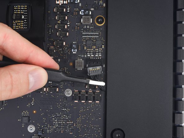
Flip the latch on the microphone ZIF connector and pull the cable out of its socket on the logic board.
My microphone stopped working after I put everything back together very very carefully. I am unsure whether or not I inserted the cable back incorrectly or damaged the cable. I did not find out the mic stopped working until I put everything back together and installed the operating system, so BE EXTRA CAREFUL with the cable! Hope this helps someone!!!
-
-
-
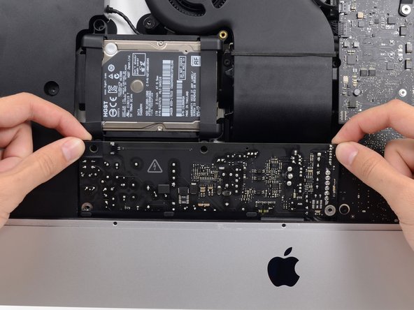
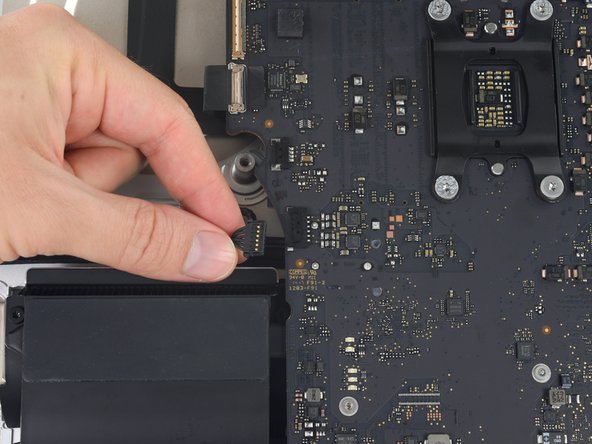
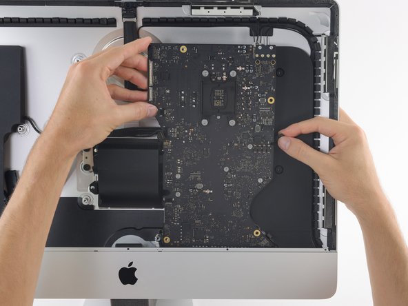
Remove the four 7.3 mm T8 Torx screws securing the logic board to the rear enclosure.
-
-
-
Lift the logic board straight up and out of the iMac.
At step 60, when reinstalling the logic board, check to make sure the I/O ports are flush with the back of the case. It’s easy to end up with a small gap, and if you do, you won’t be able to fully insert USB-C connectors.
I’d like to second this. Screw in the four logic board screws very loosley. Then make sure all the cables are where they should be. Then push the bottom of the board back until you feel it snap into place. Then tighten the four screws. At this point, before going any further, test out all the ports with some plugs to make sure everything goes in nice and easy.
Especially the USB-C's, these are the most delicate ones...
-
-
-
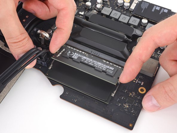
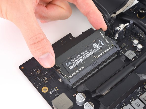
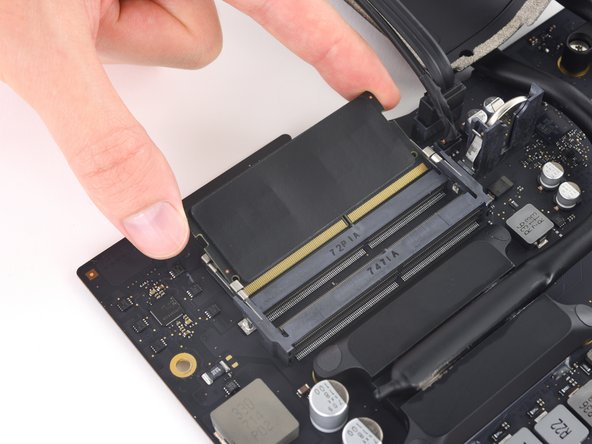
Peel off and transfer the thermal pad from the original RAM stick to your replacement RAM before you install it in the lower slot.
Wird das Display beim späteren Zusammenbau nicht frisch verklebt? Beispielsweise mit Klebestreifen?
-


To reassemble your device, follow these instructions in reverse order.
To reassemble your device, follow these instructions in reverse order.
Cancelar: não concluí este guia.
22 outras pessoas executaram este guia.


5 comentários
Be very careful. I also replaced my fusion drive with a 2T SSD and maxed the ram to 32gb but somehow I screwed up the microphone. I had to pay Apple 520.00 to fix it because they had to replace the whole back cover. Took about a week to get it back from Apple. Good luck!
Frank, along the bottom right hand side of the aluminum case where the screen slots in there are three small holes. Make sure the adhesive doesn't cover those as it is the microphone. To do this, I laid the screen adhesive, and then cut a section out over those holes.
successful upgrade my iMac to 2 TB SSD and 32gb RAM with no complications. Thank for this useful guide
Hats off team!! Really nice and helpful guide.
Done and worked on an iMac Retina 4K 2017. Upgraded SSD Crucial 2Tb MX500 + 2 x 16Gb RAM. Finished and working!!
100% satisfied with the improvement.
Please take your time and read ALL users comments. They have experienced issues that you can avoid. Use adhesive tape to fix some connectors, be careful when removing the display and check everyting works before setting the new adhesives.
Time 1h 47m. Most time consuming and delicated parts - Removing screen and adhesive and finally setting the new adhesives and fitting the screen.
The wedge is an extremely tight fit for this model. I was worried that the amount of force needed to use it as shown might damage the stand, so I used it with the long side down instead. It worked fine that way and didn’t need anywhere near as much force to insert.
roberttrevellyan - Responder
Here’s a good YouTube vid on upgrading the RAM: Can a Normal Person Upgrade the RAM in the 2017 21.5" iMac?
Dan - Responder
Here are a couple tips from me:
1) Expose the adhesive to extreme temperatures. I did this by transporting my iMac in my car, screen-down on a piece of cardboard on a cold February morning (in Chicago). When I went to pick up the iMac, the screen practically fell off the chassis. I would have been distraught by this if I hadn’t already planned this replacement. So it was a happy accident.
2) Remember to expell the residual power from the power supply by pushing the power button while the iMac is unplugged. This does NOT guarantee it’s safe to touch, but when I accidentally brushed the solder and exposed capacitors, I didn’t get shocked.
jerrid_foiles - Responder
Instead of using the wedge, I placed the iMac faced up with the top side (web cam) facing me while I ran the pizza roller around. It worked out great!
Sam Fung - Responder
“All iMacs also come with a traditional hard drive” mine doesn’t!! it’s HDD bay is completely empty, no SATA cable or anything. I guess I’ll have to upgrade the PCIe SSD instead.
Chris Hughes - Responder
There is no replacement glass for this model, it is part of the LCD and impossible to remove or replace- the entire LCD has to be replaced unfortunately if the glass is cracked or damaged. You will have to Google search for a replacement. Also be careful with some of the lock tight tork screws as I broke one of my screw mounts taking one out.
Phil Tesone - Responder
I used this service wedge but also found it a very tight fit. The same stabilization can be achieved by using a big rolled up towel.
Ernst - Responder
While this is a good instruction guide, I recommend to also look at OWC’s instruction video about drive installation, before starting the exercise. Those install videos are very detailed and useful.
Ernst - Responder
Main advice: TAKE YOUR TIME with the pizza roller.
Make several passes, until you really feel like there's no more sticker in the way. Stay away from the camera though (approx. 1inch / 2.5cm on both sides). This will reduce the work left with the plastic card. Adhesive is really on the edge of the screen so there is absolutely no need to go any further than the recommended 1cm / 3/8inch depth.
Where are the sensitive parts?
Facing your iMac, imagine you're looking at a watch. There are antennas on 1, 2 and 4 o'clock. Do not insert any metal piece there (nor anywhere else, btw). Other than that AND the screen cables underneath the camera, not much danger.
Froggy Manny - Responder