Esta versão pode conter edições incorretas. Mude para o último instantâneo verificado.
O que você precisa
-
-
-
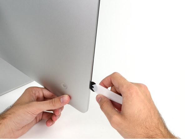
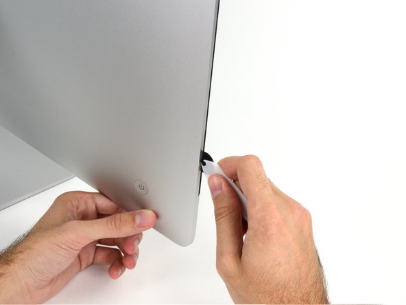
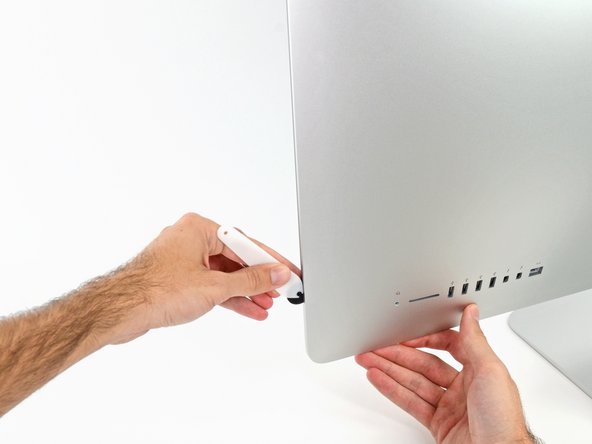
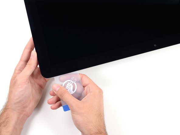
Este passo não foi traduzido. Ajude a traduzi-lo
-
Remove the following five Phillips screws holding the lower support bracket in place:
-
Four 3.2 mm screws
-
One 1.7 mm screw
-
-
Este passo não foi traduzido. Ajude a traduzi-lo
-
Remove the lower support bracket (a.k.a. "chin strap") from the iMac enclosure.
-
-
Este passo não foi traduzido. Ajude a traduzi-lo
-
Remove the following T10 Torx screws securing the hard drive brackets to the iMac:
-
Two 21 mm screws
-
One 9 mm screw
-
One 27 mm screw
-
-
Este passo não foi traduzido. Ajude a traduzi-lo
-
Remove the left and right hard drive brackets from the iMac.
-
-
Este passo não foi traduzido. Ajude a traduzi-lo
-
Use the tip of a spudger to push each side of the power button cable connector and gently walk it out of its socket.
-
-
Este passo não foi traduzido. Ajude a traduzi-lo
-
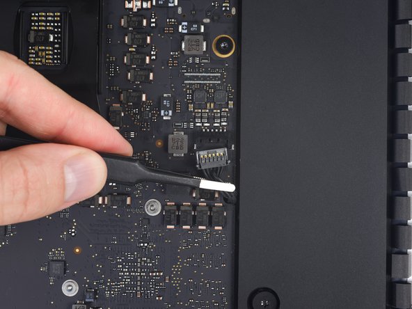
Use the tip of a spudger to push each side of the power supply control cable connector and gently walk it out of its socket.
-
-
Este passo não foi traduzido. Ajude a traduzi-lo
-
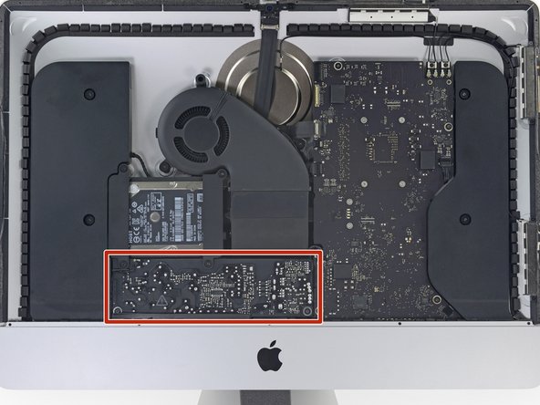
Remove the two 7.2 mm T10 Torx screws securing the power supply to the rear enclosure.
-
-
Este passo não foi traduzido. Ajude a traduzi-lo
-
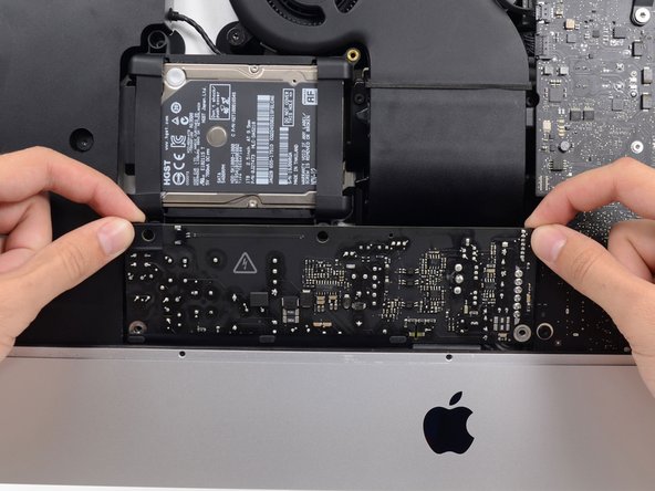
Pull the power supply slightly up and out from the rear enclosure.
-
Rotate the power supply counterclockwise, lifting the right side up about an inch higher than the left.
-
-
Este passo não foi traduzido. Ajude a traduzi-lo
-
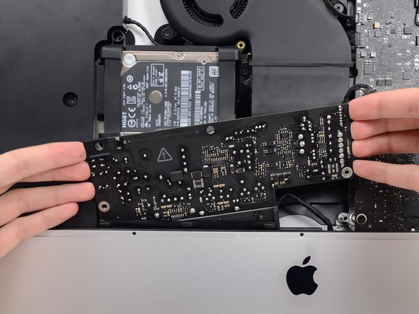
Slide the power supply to the right to clear the screw posts on the rear enclosure.
-
-
Este passo não foi traduzido. Ajude a traduzi-lo
-
Rock the power supply forward and remove it from its recess in the rear enclosure.
-
-
Este passo não foi traduzido. Ajude a traduzi-lo
-
Squeeze the tab on the back side of the DC power cable connector and pull it straight out of its socket on the back of the logic board.
-
-
Este passo não foi traduzido. Ajude a traduzi-lo
-
Use the flat end of a spudger to press the clip on the side of the AC inlet cable connector inward.
-
While pressing on the release clip with the spudger, grasp the AC inlet cable, and pull the connector straight out of its socket.
-
-
Este passo não foi traduzido. Ajude a traduzi-lo
-
Gently pull the fan cable connector straight away from its socket on the logic board.
-
-
Este passo não foi traduzido. Ajude a traduzi-lo
-
Remove the three 10 mm T10 Torx screws securing the fan to the rear enclosure.
-
-
Este passo não foi traduzido. Ajude a traduzi-lo
-
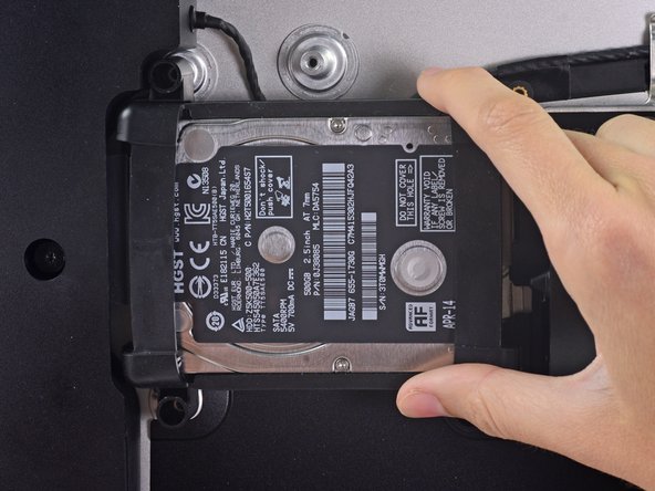
Lift the hard drive from the edge nearest the logic board and pull it slightly out of its recess.
-
-
Este passo não foi traduzido. Ajude a traduzi-lo
-
Use a spudger to disconnect the single SATA power and data combo cable by gently prying its large plastic connector away from the hard drive.
-
-
Este passo não foi traduzido. Ajude a traduzi-lo
-
Remove the 7.3 mm T8 Torx screw securing the hard drive tray to the rear enclosure.
-
-
Este passo não foi traduzido. Ajude a traduzi-lo
-
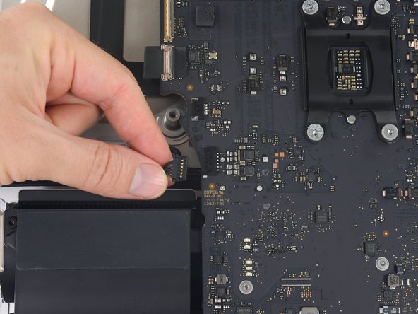
Gently pull the right speaker cable connector straight down and out of its socket on the logic board.
-
-
Este passo não foi traduzido. Ajude a traduzi-lo
-
Gently pull the left speaker cable straight out of its socket on the logic board.
-
-
Este passo não foi traduzido. Ajude a traduzi-lo
-
De-route the left speaker cable by pulling it straight up out of the retaining clip in the back of the rear enclosure.
-
-
Este passo não foi traduzido. Ajude a traduzi-lo
-
Similarly to the previous step, de-route the SATA and power cables by pulling the braid straight up out of the retaining clip.
-
-
Este passo não foi traduzido. Ajude a traduzi-lo
-
Peel up the piece of tape connecting the left speaker connector to the SATA power and data cables.
-
-
Este passo não foi traduzido. Ajude a traduzi-lo
-
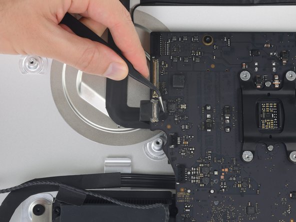
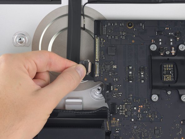
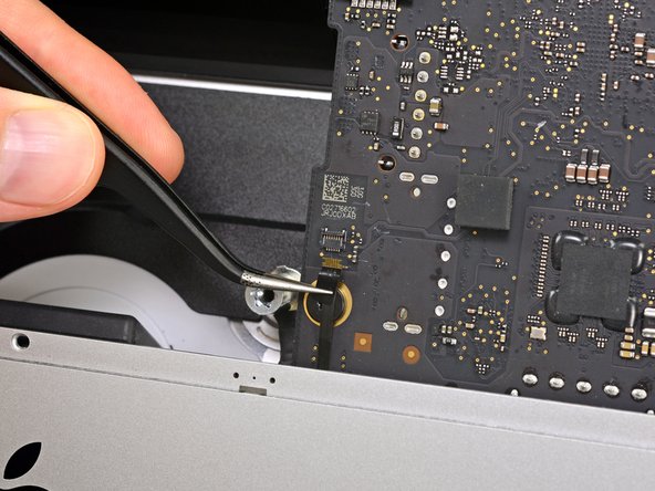
Flip up the metal retaining bracket on the FaceTime camera cable connector.
-
Pull the FaceTime camera cable straight out of its socket on the logic board.
-
-
Este passo não foi traduzido. Ajude a traduzi-lo
-
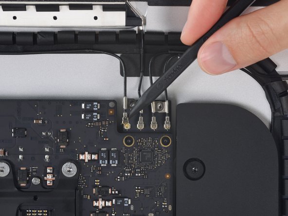
Remove the two 4.0 mm T5 Torx screws securing the four antenna connectors to the AirPort/Bluetooth card.
-
-
Este passo não foi traduzido. Ajude a traduzi-lo
-
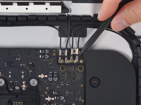
Disconnect all four antenna connectors by prying them straight up from their sockets on the AirPort/Bluetooth card.
-
-
Este passo não foi traduzido. Ajude a traduzi-lo
-
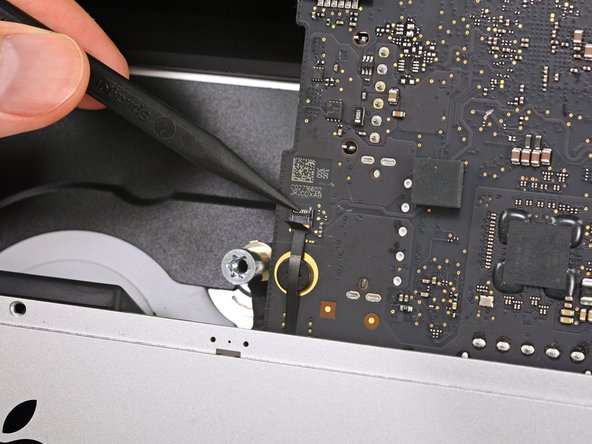
Use the flat edge of a spudger to pry the headphone jack cable connector from its socket on the logic board.
-
Push the cable up and out of the way of the logic board.
-
-
Este passo não foi traduzido. Ajude a traduzi-lo
-
Remove the following T8 Torx screws securing the exhaust duct to the rear enclosure:
-
Two 6.2 mm screws
-
Two 4.7 mm screws
-
-
Este passo não foi traduzido. Ajude a traduzi-lo
-
Flip the latch on the microphone ZIF connector and pull the cable out of its socket on the logic board.
-
-
Este passo não foi traduzido. Ajude a traduzi-lo
-
Remove the four 7.3 mm T8 Torx screws securing the logic board to the rear enclosure.
-
-
Este passo não foi traduzido. Ajude a traduzi-lo
-
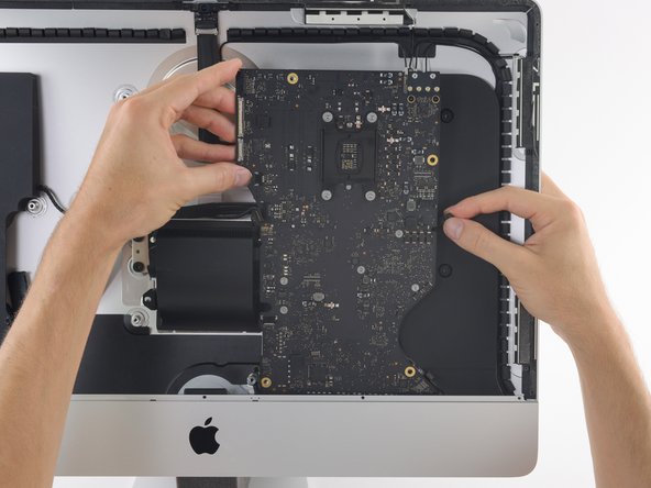
Tilt the top of the logic board away from the rear enclosure.
-
-
Este passo não foi traduzido. Ajude a traduzi-lo
-
Lift the logic board straight up and out of the iMac.
-
-
Este passo não foi traduzido. Ajude a traduzi-lo
-
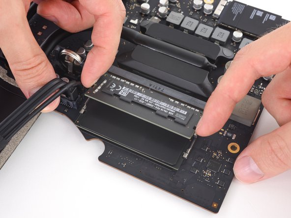
Handling the board by the edges, flip the logic board over to access the two RAM modules.
-
-
Este passo não foi traduzido. Ajude a traduzi-lo
-
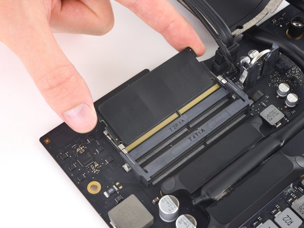
Two clips secure the RAM module in place, one on each side. Using your fingers, spread the clips away from the RAM module.
-
-
Este passo não foi traduzido. Ajude a traduzi-lo
-
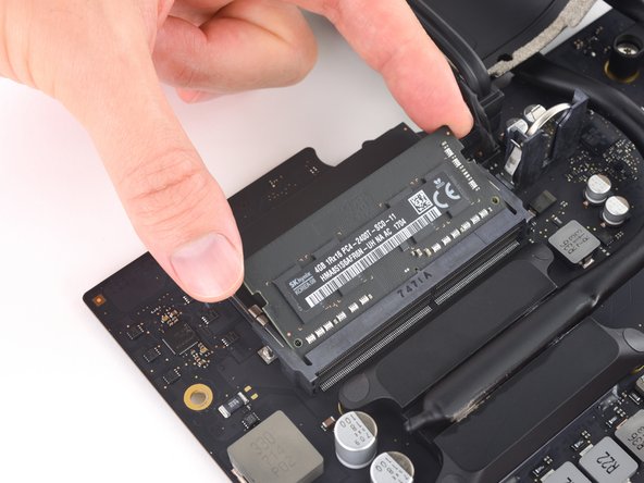
Lift the RAM module to an angle of about 30 degrees and slide it out.
-
-
Este passo não foi traduzido. Ajude a traduzi-lo
-
Peel off and transfer the thermal pad from the original RAM stick to your replacement RAM before you install it in the lower slot.
-


Cancelar: não concluí este guia.
146 outras pessoas executaram este guia.

77 comentários
An excellent guide - many thanks. The logic board was tricksy to get out - the card reader was jamming on the casing, but it came out with care. It's easy to trap the microphone cable and the power button cables when re-assembling, so they're worth looking out for. Successfully replaced the RAM and installed an SSD at the same time - many thanks.
Can a SSD or fusion drive be put in the place where the normal hard drive was?
An ssd can yes - that's what I did at the same time as upgrading the ram. As long as it's a 2.5" ssd it should be fine. The Samsung ssd I used was a but thinner than the hard drive that came out but that doesn't affect anything really. You'll need to either have a bootable clone of your drive, or install Sierra from a USB stick you've already prepared (which is what I did).
A Fusion drive is the terminology used by Apple when the use a board soldered 120ish Gb storage and a standard 1Tb 2.5 inch drive, and bind them together, if you throw in a 1Tb SSD in place of the existing standard hard drive you end up with 2 drives when you begin installation, you can find the instructions to merge the onboard and the new SSD back together again, and boy does it transform these machines, absolute pig with a factory fusion setup.
I also upgraded my hard-drive to a 512 GB Samsung SSD successfully along with installing the 32 GB of RAM. The guide was great, but I have a two comments.
1) The screws that hold the antenna connectors (Step 52) are were very tightly screwed into the board, and it is easy to strip the head of the screw. I stripped one of the screws… Luckily, it was easy to just pull up on the bluetooth/AirPort card and slide it out from its slot on the main board. Thus, an option to removing all the antenna wires, is to just pull the bluetooth/Airport card out. It was quite easy to slip back into the correct spot when reassembling as well.
2) It was only after I completed the repair that I realized that the top of the nice screwdriver provided in the repair kit contained more hidden bits!