Ir para o conteúdo principal

Esta versão pode conter edições incorretas. Mude para o último instantâneo verificado.

Pré-requisito somente
Este guia destina-se apenas a ser usado como pré-requisito para outros guias. É incompleto por si só.

O que você precisa

  1. Este passo não foi traduzido. Ajude a traduzi-lo

    : passo 1, imagem 1 %32 : passo 1, imagem 2 %32
    • Peel off the four black tamper-evident stickers covering the heat sink mounting screws.

    • Remove the four T10 screws that secure the heat sink from the backside of the logic board.

    • During reassembly, tighten these screws one full turn at a time, alternating in a cross pattern. This will gradually increase the clamping pressure evenly across the surface of the CPU. Continue gradually tightening the screws until they're snug and the entire spring plate lays flat against the logic board.

  2. Este passo não foi traduzido. Ajude a traduzi-lo

    : passo 2, imagem 1 %32 : passo 2, imagem 2 %32
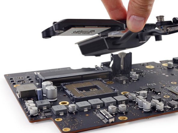
    • Lift the heat sink retaining spring and its bracket off the logic board.

  3. Este passo não foi traduzido. Ajude a traduzi-lo

    : passo 3, imagem 1 %32
    • Fully loosen the three captive T8 screws securing the heat sink over the GPU.

    • Remove the two 5.4 mm T8 screws securing the heat pipe to the logic board.

  4. Este passo não foi traduzido. Ajude a traduzi-lo

    : passo 4, imagem 1 %32 : passo 4, imagem 2 %32
    • Note that the CPU will most likely remain stuck to the underside of the heat sink as it's lifted out. Take care not to damage it.

    • Lift and remove the heat sink assembly from the logic board.

Linha de Chegada

Adam O'Camb

Membro desde: 04/11/15

196.767 Reputação

Autoria de 416 guias

0 comentários

Adicione um comentário

Exibir estatísticas:

Últimas 24 horas: 0

Últimos 7 dias: 4

Últimos 30 dias: 4

Duração total: 48