Esta versão pode conter edições incorretas. Mude para o último instantâneo verificado.
O que você precisa
-
Este passo não foi traduzido. Ajude a traduzi-lo
-
Before beginning any work on your iMac: Unplug the computer and press and hold the power button for ten seconds to discharge the power supply's capacitors.
-
-
Este passo não foi traduzido. Ajude a traduzi-lo
-
Starting on the left of the display, near the power button, insert the iMac Opening Tool into the gap between the glass panel and the rear enclosure.
-
-
Este passo não foi traduzido. Ajude a traduzi-lo
-
Use the tool like a pizza cutter—roll it along through the gap, and it will cut the foam adhesive through the center.
-
Run the tool up along the left side of the display.
-
-
Este passo não foi traduzido. Ajude a traduzi-lo
-
Continue running the tool up around the top left corner.
-
-
Este passo não foi traduzido. Ajude a traduzi-lo
-
Cut the adhesive along the top left of the display.
-
-
Este passo não foi traduzido. Ajude a traduzi-lo
-
Push the tool around the top right corner of the display.
-
-
Este passo não foi traduzido. Ajude a traduzi-lo
-
Wheel the tool down along the right side of the display.
-
-
Este passo não foi traduzido. Ajude a traduzi-lo
-
Finish pushing the opening tool to the bottom of the right side of the display.
-
-
Este passo não foi traduzido. Ajude a traduzi-lo
-
Starting from the top right corner of the iMac, wedge a plastic card between the display and frame.
-
-
Este passo não foi traduzido. Ajude a traduzi-lo
-
Gently twist the plastic card sideways to create a gap between the display and frame.
-
Move slowly and be careful not to stress the display glass too much—you only need to make a gap of about 1/4".
-
-
Este passo não foi traduzido. Ajude a traduzi-lo
-
Slide the card toward the center of the display to cut any of the remaining adhesive along the top right corner of the iMac.
-
-
Este passo não foi traduzido. Ajude a traduzi-lo
-
Wedge the plastic card into the top right corner once again, and leave it there to prevent the adhesive from resticking.
-
-
Este passo não foi traduzido. Ajude a traduzi-lo
-
Insert a second plastic card into the gap between the display and frame near the top left corner of the iMac.
-
-
Este passo não foi traduzido. Ajude a traduzi-lo
-
Gently twist the card upward, slightly increasing the space between the display and frame.
-
-
Este passo não foi traduzido. Ajude a traduzi-lo
-
Slide the plastic card toward the center, again stopping just before the iSight camera.
-
-
Este passo não foi traduzido. Ajude a traduzi-lo
-
Wedge the plastic card back into the top left corner.
-
-
Este passo não foi traduzido. Ajude a traduzi-lo
-
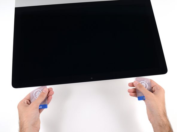
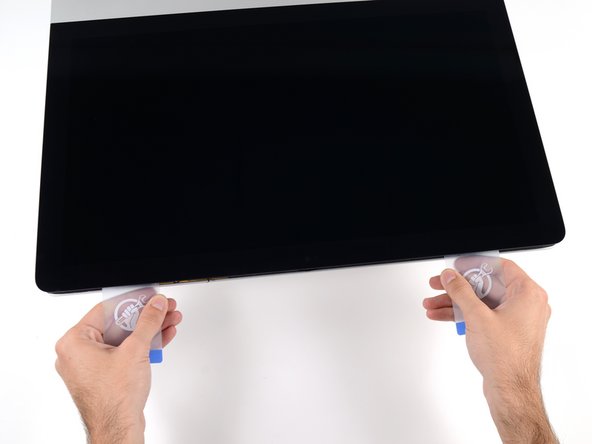
With both plastic cards inserted as shown near the corners, gently twist the cards sideways to increase the gap between display and case.
-
Begin to lift the top of the display up from the frame.
-
-
Este passo não foi traduzido. Ajude a traduzi-lo
-
Hold the display with one hand while using your other hand to unplug the display power cable.
-
-
Este passo não foi traduzido. Ajude a traduzi-lo
-
Continuing to support the display with one hand, flip up the metal retaining bracket on the display data cable.
-
Carefully pull the display data cable from its socket on the logic board.
-
-
Este passo não foi traduzido. Ajude a traduzi-lo
-
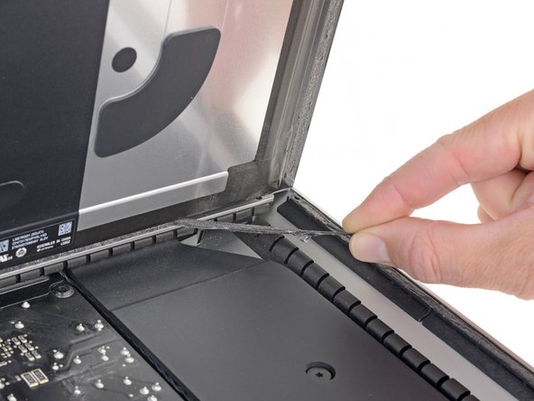
Grasp the small tab at the end of one of the bottom edge display adhesive strips and pull the adhesive toward the top of the iMac to remove it.
-
Repeat this step with the other adhesive strip and remove it.
-
-
Este passo não foi traduzido. Ajude a traduzi-lo
-
Lift the display up from the frame and remove it from the iMac.
-
It may be necessary to slowly lift from one side to peel against the remaining adhesive.
-
-
Este passo não foi traduzido. Ajude a traduzi-lo
-
Remove the following five Phillips screws holding the lower support bracket in place:
-
Four 3.2 mm screws
-
One 1.7 mm screw
-
-
Este passo não foi traduzido. Ajude a traduzi-lo
-
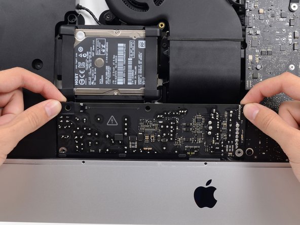
Remove the lower support bracket (a.k.a. "chin strap") from the iMac enclosure.
-
-
-
Este passo não foi traduzido. Ajude a traduzi-lo
-
Remove the following T10 Torx screws securing the hard drive brackets to the iMac:
-
Two 21 mm screws
-
One 9 mm screw
-
One 27 mm screw
-
-
Este passo não foi traduzido. Ajude a traduzi-lo
-
Remove the left and right hard drive brackets from the iMac.
-
-
Este passo não foi traduzido. Ajude a traduzi-lo
-
Use the tip of a spudger to push each side of the power button cable connector and gently walk it out of its socket.
-
-
Este passo não foi traduzido. Ajude a traduzi-lo
-
Use the tip of a spudger to push each side of the power supply control cable connector and gently walk it out of its socket.
-
-
Este passo não foi traduzido. Ajude a traduzi-lo
-
Remove the two 7.2 mm T8 Torx screws securing the power supply to the rear enclosure.
-
-
Este passo não foi traduzido. Ajude a traduzi-lo
-
Pull the power supply slightly up and out from the rear enclosure.
-
Rotate the power supply counterclockwise, lifting the right side up about an inch higher than the left.
-
-
Este passo não foi traduzido. Ajude a traduzi-lo
-
Slide the power supply to the right to clear the screw posts on the rear enclosure.
-
-
Este passo não foi traduzido. Ajude a traduzi-lo
-
Rock the power supply forward and remove it from its recess in the rear enclosure.
-
-
Este passo não foi traduzido. Ajude a traduzi-lo
-
To disconnect the cable, squeeze the release clip on the back side of the connector, behind the logic board, and pull the connector straight out.
-
-
Este passo não foi traduzido. Ajude a traduzi-lo
-
Use the flat end of a spudger to press the release clip on the side of the AC inlet cable connector inward.
-
While pressing on the release clip with the spudger, grasp the AC inlet cable, and pull the connector straight out of its socket.
-
-
Este passo não foi traduzido. Ajude a traduzi-lo
-
Gently pull the fan cable connector straight out of its socket on the logic board.
-
-
Este passo não foi traduzido. Ajude a traduzi-lo
-
Remove the three 10 mm T10 Torx screws securing the fan to the rear enclosure.
-
-
Este passo não foi traduzido. Ajude a traduzi-lo
-
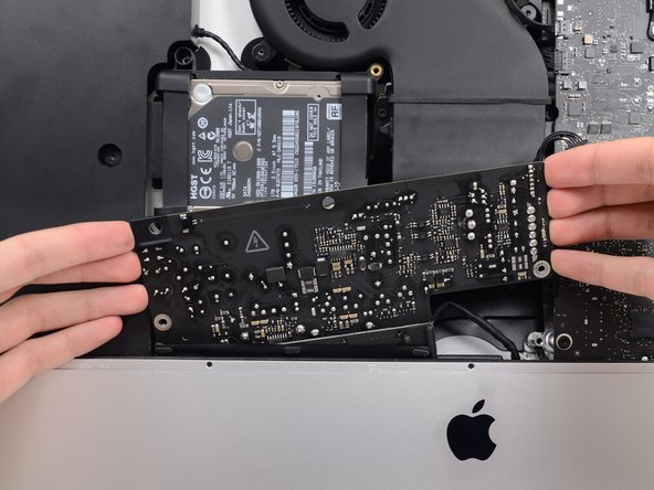
Lift the hard drive from the edge nearest the logic board and pull it slightly out of its recess.
-
-
Este passo não foi traduzido. Ajude a traduzi-lo
-
Use a spudger to disconnect the single SATA power and data combo cable by gently prying its large plastic connector away from the hard drive.
-
-
Este passo não foi traduzido. Ajude a traduzi-lo
-
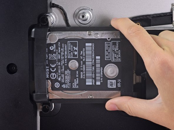
Remove the 7.3 mm T8 Torx screw securing the hard drive tray to the rear enclosure.
-
-
Este passo não foi traduzido. Ajude a traduzi-lo
-
Gently pull the left speaker cable straight out of its socket on the logic board.
-
-
Este passo não foi traduzido. Ajude a traduzi-lo
-
De-route the left speaker cable by pulling it straight up out of the retaining clip in the back of the rear enclosure.
-
-
Este passo não foi traduzido. Ajude a traduzi-lo
-
Similarly to the previous step, de-route the SATA and power cables by pulling the braid straight up out of the retaining clip.
-
-
Este passo não foi traduzido. Ajude a traduzi-lo
-
Peel up the piece of tape connecting the left speaker connector to the SATA power and data cables.
-
-
Este passo não foi traduzido. Ajude a traduzi-lo
-
Flip up the metal retaining bracket on the FaceTime camera cable connector.
-
Pull the FaceTime camera cable straight out of its socket on the logic board.
-
-
Este passo não foi traduzido. Ajude a traduzi-lo
-
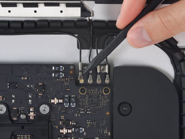
Remove the two 4.0 mm T5 Torx screws securing the four antenna connectors to the AirPort/Bluetooth card.
-
-
Este passo não foi traduzido. Ajude a traduzi-lo
-
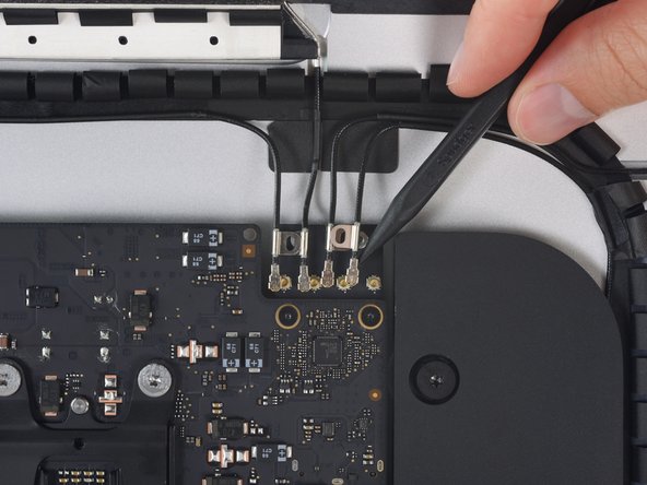
Disconnect all four antenna connectors by prying them straight up from their sockets on the AirPort/Bluetooth card.
-
-
Este passo não foi traduzido. Ajude a traduzi-lo
-
Gently pull the right speaker cable connector straight down and out of its socket on the logic board.
-
-
Este passo não foi traduzido. Ajude a traduzi-lo
-
Use the flat edge of a spudger to pry the headphone jack cable connector from its socket on the logic board.
-
-
Este passo não foi traduzido. Ajude a traduzi-lo
-
Remove the following T8 Torx screws securing the exhaust duct to the rear enclosure:
-
Two 6.2 mm screws
-
Two 4.7 mm screws
-
-
Este passo não foi traduzido. Ajude a traduzi-lo
-
Use the tip of a spudger to flip open the retaining flap on the microphone ribbon cable ZIF socket.
-
Gently pull the microphone ribbon cable straight out of its socket.
-
-
Este passo não foi traduzido. Ajude a traduzi-lo
-
Remove the four 7.3 mm T8 Torx screws securing the logic board to the rear enclosure.
-
-
Este passo não foi traduzido. Ajude a traduzi-lo
-
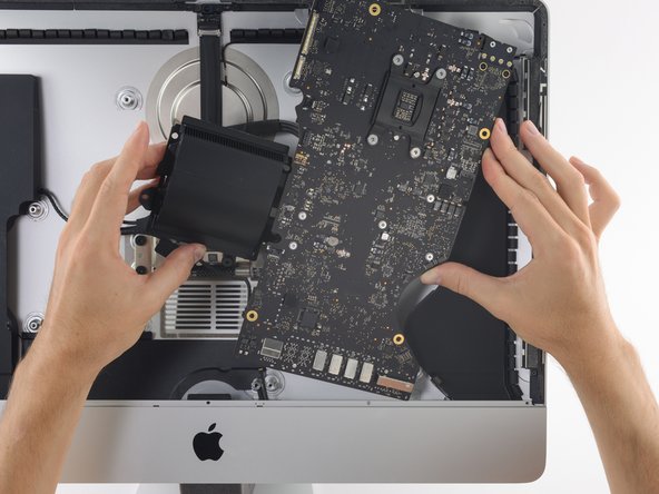
Tilt the top of the logic board away from the rear enclosure.
-
As you tilt the logic board, pull the right speaker connector to the right and out of the way of the board.
-
Lift the logic board straight up and out of the iMac.
-
-
Este passo não foi traduzido. Ajude a traduzi-lo
-
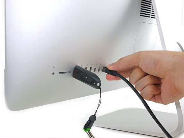
Use a USB flash drive and/or ethernet cable to keep the logic board seated correctly while you tighten the screws.
-
-
Este passo não foi traduzido. Ajude a traduzi-lo
-
While pressing on the clip with your thumb, lift and disconnect the SATA data connector from its socket on the logic board.
-
-
Este passo não foi traduzido. Ajude a traduzi-lo
-
Grasp the hard drive power connector and gently pull it out of its socket on the logic board.
-
-
Este passo não foi traduzido. Ajude a traduzi-lo
-
Peel off the four black tamper-evident stickers covering the heat sink mounting screws.
-
Remove the four T10 screws that secure the heat sink from the backside of the logic board.
-
-
Este passo não foi traduzido. Ajude a traduzi-lo
-
Lift the heat sink retaining spring and its bracket off the logic board.
-
-
Este passo não foi traduzido. Ajude a traduzi-lo
-
Fully loosen the three captive T8 screws securing the heat sink over the GPU.
-
Remove the two 5.4 mm T8 screws securing the heat pipe to the logic board.
-
-
Este passo não foi traduzido. Ajude a traduzi-lo
-
Lift and remove the heat sink assembly from the logic board.
-
-
Este passo não foi traduzido. Ajude a traduzi-lo
-
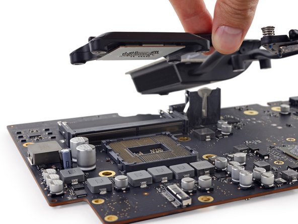
Flip the heat sink over and use your spudger to pry out the CPU, being careful not to drop it.
-
-
Este passo não foi traduzido. Ajude a traduzi-lo
-
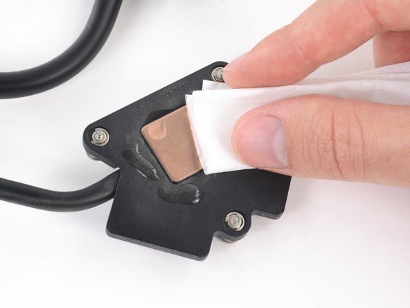
Use a lint-free cloth (or coffee filter) with either isopropyl alcohol or ArctiClean Thermal Material Remover to thoroughly clean the thermal paste residue from both the CPU and GPU arms of the heat sink.
-
Once the heat sink surfaces are completely clean, use a fresh lint-free cloth or coffee filter to apply a drop of ArctiClean Thermal Surface Purifier to remove any oils and prepare the copper heat sink surfaces.
-
Allow the heat sink to dry completely while you continue working.
-
-
Este passo não foi traduzido. Ajude a traduzi-lo
-
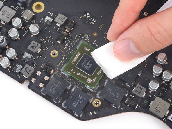
Use a spudger to gently lift the excess thermal paste residue off of the GPU.
-
As before, use a lint-free cloth or coffee filter and the appropriate fluids to clean and prep the GPU surface.
-
Clean the thermal paste from the four VRAM chips around the GPU as well.
-
-
Este passo não foi traduzido. Ajude a traduzi-lo
-
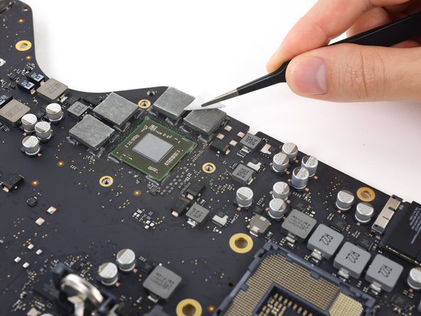
Apply thermal pads to the four VRAM modules around the GPU.
-
Use tweezers to peel the liner from the tops of the thermal pads.
-
-
Este passo não foi traduzido. Ajude a traduzi-lo
-
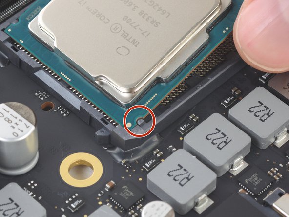
Small cutouts on the edges of the CPU align with notches on the sides of the socket.
-
Carefully align your new CPU into its socket on the motherboard, and lay it into position.
-
-
Este passo não foi traduzido. Ajude a traduzi-lo
-
Follow the instructions specific to your CPU type to apply fresh thermal paste to the surface of your CPU.
-


Cancelar: não concluí este guia.
19 outras pessoas executaram este guia.

36 comentários
Can I upgrade to i7 7700K on iMac 2017 21.5inch ?
looking at the compare on intel’s website:
https://ark.intel.com/compare/97128,9712...
the 7700k being a 130w vs any Apple installed CPU being 65W, I’d think the the likelihood to overheat or draw too much power would be high but I don’t have enough experience to know for certain.
Benjamin -
Hey Mikkser, 8-series (Coffee Lake) CPUs require the Z370 chipset, which to my knowledge isn’t on the 2017 iMac logic boards. The socket is the same as the last generation so you’d be able to plug an 8700K in, but it wouldn’t work.