Esta versão pode conter edições incorretas. Mude para o último instantâneo verificado.
O que você precisa
-
Este passo não foi traduzido. Ajude a traduzi-lo
-
Before beginning any work on your iMac: Unplug the computer and press and hold the power button for ten seconds to discharge the power supply's capacitors.
-
-
Este passo não foi traduzido. Ajude a traduzi-lo
-
Starting on the left of the display, near the power button, insert the iMac Opening Tool into the gap between the glass panel and the rear enclosure.
-
-
Este passo não foi traduzido. Ajude a traduzi-lo
-
Use the tool like a pizza cutter—roll it along through the gap, and it will cut the foam adhesive through the center.
-
Run the tool up along the left side of the display.
-
-
Este passo não foi traduzido. Ajude a traduzi-lo
-
Continue running the tool up around the top left corner.
-
-
Este passo não foi traduzido. Ajude a traduzi-lo
-
Cut the adhesive along the top left of the display.
-
-
Este passo não foi traduzido. Ajude a traduzi-lo
-
Push the tool around the top right corner of the display.
-
-
Este passo não foi traduzido. Ajude a traduzi-lo
-
Wheel the tool down along the right side of the display.
-
-
Este passo não foi traduzido. Ajude a traduzi-lo
-
Finish pushing the opening tool to the bottom of the right side of the display.
-
-
Este passo não foi traduzido. Ajude a traduzi-lo
-
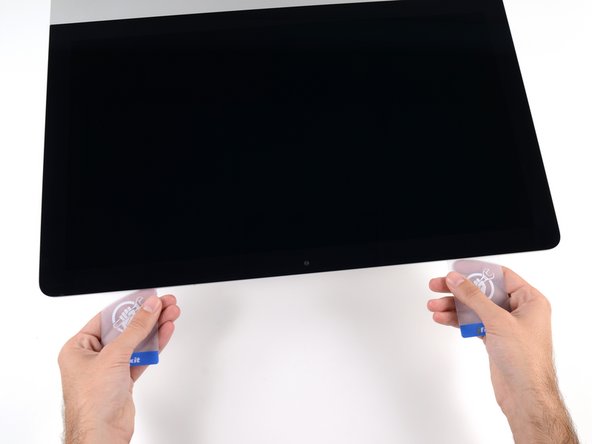
Starting from the top right corner of the iMac, wedge a plastic card between the display and frame.
-
-
Este passo não foi traduzido. Ajude a traduzi-lo
-
Gently twist the plastic card sideways to create a gap between the display and frame.
-
Move slowly and be careful not to stress the display glass too much—you only need to make a gap of about 1/4".
-
-
Este passo não foi traduzido. Ajude a traduzi-lo
-
Slide the card toward the center of the display to cut any of the remaining adhesive along the top right corner of the iMac.
-
-
Este passo não foi traduzido. Ajude a traduzi-lo
-
Wedge the plastic card into the top right corner once again, and leave it there to prevent the adhesive from resticking.
-
-
Este passo não foi traduzido. Ajude a traduzi-lo
-
Insert a second plastic card into the gap between the display and frame near the top left corner of the iMac.
-
-
Este passo não foi traduzido. Ajude a traduzi-lo
-
Gently twist the card upward, slightly increasing the space between the display and frame.
-
-
Este passo não foi traduzido. Ajude a traduzi-lo
-
Slide the plastic card toward the center, again stopping just before the iSight camera.
-
-
Este passo não foi traduzido. Ajude a traduzi-lo
-
Wedge the plastic card back into the top left corner.
-
-
Este passo não foi traduzido. Ajude a traduzi-lo
-
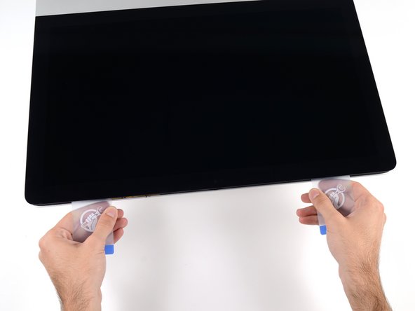
With both plastic cards inserted as shown near the corners, gently twist the cards sideways to increase the gap between display and case.
-
Begin to lift the top of the display up from the frame.
-
-
Este passo não foi traduzido. Ajude a traduzi-lo
-
Hold the display with one hand while using your other hand to unplug the display power cable.
-
-
Este passo não foi traduzido. Ajude a traduzi-lo
-
Continuing to support the display with one hand, flip up the metal retaining bracket on the display data cable.
-
Carefully pull the display data cable from its socket on the logic board.
-
-
-
Este passo não foi traduzido. Ajude a traduzi-lo
-
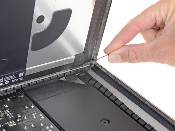
Grasp the small tab at the end of one of the bottom edge display adhesive strips and pull the adhesive toward the top of the iMac to remove it.
-
Repeat this step with the other adhesive strip and remove it.
-
-
Este passo não foi traduzido. Ajude a traduzi-lo
-
Lift the display up from the frame and remove it from the iMac.
-
It may be necessary to slowly lift from one side to peel against the remaining adhesive.
-
-
Este passo não foi traduzido. Ajude a traduzi-lo
-
Remove the following five Phillips screws holding the lower support bracket in place:
-
Four 3.2 mm screws
-
One 1.7 mm screw
-
-
Este passo não foi traduzido. Ajude a traduzi-lo
-
Remove the lower support bracket (a.k.a. "chin strap") from the iMac enclosure.
-
-
Este passo não foi traduzido. Ajude a traduzi-lo
-
Remove the following T10 Torx screws securing the hard drive brackets to the iMac:
-
Two 21 mm screws
-
One 9 mm screw
-
One 27 mm screw
-
-
Este passo não foi traduzido. Ajude a traduzi-lo
-
Remove the left and right hard drive brackets from the iMac.
-
-
Este passo não foi traduzido. Ajude a traduzi-lo
-
Use the tip of a spudger to push each side of the power button cable connector and gently walk it out of its socket.
-
-
Este passo não foi traduzido. Ajude a traduzi-lo
-
Use the tip of a spudger to push each side of the power supply control cable connector and gently walk it out of its socket.
-
-
Este passo não foi traduzido. Ajude a traduzi-lo
-
Remove the two 7.2 mm T8 Torx screws securing the power supply to the rear enclosure.
-
-
Este passo não foi traduzido. Ajude a traduzi-lo
-
Pull the power supply slightly up and out from the rear enclosure.
-
Rotate the power supply counterclockwise, lifting the right side up about an inch higher than the left.
-
-
Este passo não foi traduzido. Ajude a traduzi-lo
-
Slide the power supply to the right to clear the screw posts on the rear enclosure.
-
-
Este passo não foi traduzido. Ajude a traduzi-lo
-
Rock the power supply forward and remove it from its recess in the rear enclosure.
-
-
Este passo não foi traduzido. Ajude a traduzi-lo
-
To disconnect the cable, squeeze the release clip on the back side of the connector, behind the logic board, and pull the connector straight out.
-
-
Este passo não foi traduzido. Ajude a traduzi-lo
-
Use the flat end of a spudger to press the release clip on the side of the AC inlet cable connector inward.
-
While pressing on the release clip with the spudger, grasp the AC inlet cable, and pull the connector straight out of its socket.
-
-
Este passo não foi traduzido. Ajude a traduzi-lo
-
Gently pull the fan cable connector straight out of its socket on the logic board.
-
-
Este passo não foi traduzido. Ajude a traduzi-lo
-
Remove the three 10 mm T10 Torx screws securing the fan to the rear enclosure.
-
-
Este passo não foi traduzido. Ajude a traduzi-lo
-
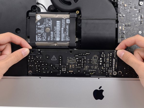
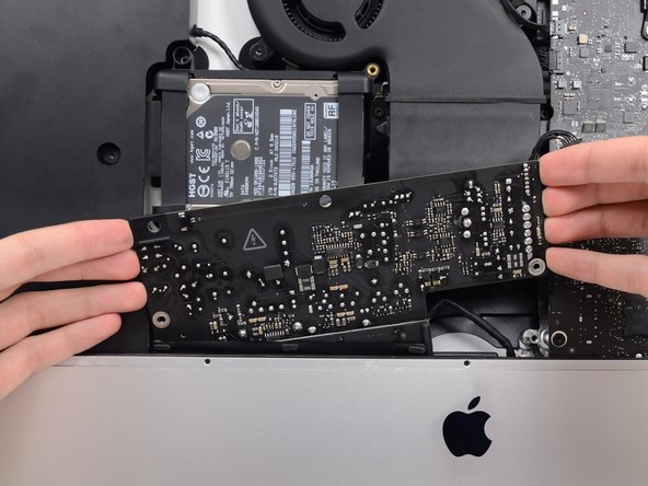
Lift the hard drive from the edge nearest the logic board and pull it slightly out of its recess.
-
-
Este passo não foi traduzido. Ajude a traduzi-lo
-
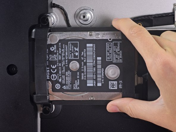
Use a spudger to disconnect the single SATA power and data combo cable by gently prying its large plastic connector away from the hard drive.
-
-
Este passo não foi traduzido. Ajude a traduzi-lo
-
Remove the 7.3 mm T8 Torx screw securing the hard drive tray to the rear enclosure.
-
-
Este passo não foi traduzido. Ajude a traduzi-lo
-
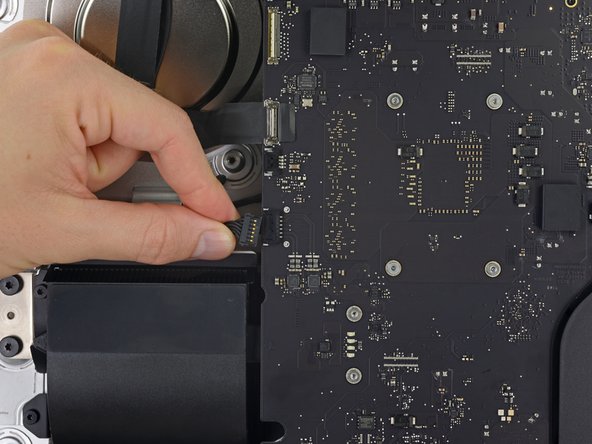
Gently pull the left speaker cable straight out of its socket on the logic board.
-
-
Este passo não foi traduzido. Ajude a traduzi-lo
-
De-route the left speaker cable by pulling it straight up out of the retaining clip in the back of the rear enclosure.
-
-
Este passo não foi traduzido. Ajude a traduzi-lo
-
Similarly to the previous step, de-route the SATA and power cables by pulling the braid straight up out of the retaining clip.
-
-
Este passo não foi traduzido. Ajude a traduzi-lo
-
Peel up the piece of tape connecting the left speaker connector to the SATA power and data cables.
-
-
Este passo não foi traduzido. Ajude a traduzi-lo
-
Flip up the metal retaining bracket on the FaceTime camera cable connector.
-
Pull the FaceTime camera cable straight out of its socket on the logic board.
-
-
Este passo não foi traduzido. Ajude a traduzi-lo
-
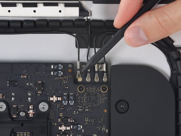
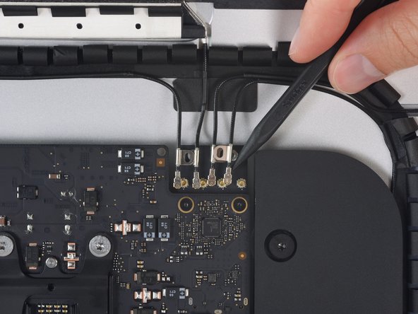
Remove the two 4.0 mm T5 Torx screws securing the four antenna connectors to the AirPort/Bluetooth card.
-
-
Este passo não foi traduzido. Ajude a traduzi-lo
-
Disconnect all four antenna connectors by prying them straight up from their sockets on the AirPort/Bluetooth card.
-
-
Este passo não foi traduzido. Ajude a traduzi-lo
-
Gently pull the right speaker cable connector parallel to the logic board, straight out of its socket on the logic board.
-
-
Este passo não foi traduzido. Ajude a traduzi-lo
-
Use the flat edge of a spudger to pry the headphone jack cable connector from its socket on the logic board.
-
-
Este passo não foi traduzido. Ajude a traduzi-lo
-
Remove the following T8 Torx screws securing the exhaust duct to the rear enclosure:
-
Two 6.2 mm screws
-
Two 4.7 mm screws
-
-
Este passo não foi traduzido. Ajude a traduzi-lo
-
Use the tip of a spudger to flip open the retaining flap on the microphone ribbon cable ZIF socket.
-
Gently pull the microphone ribbon cable straight out of its socket.
-
-
Este passo não foi traduzido. Ajude a traduzi-lo
-
Remove the four 7.3 mm T8 Torx screws securing the logic board to the rear enclosure.
-
-
Este passo não foi traduzido. Ajude a traduzi-lo
-
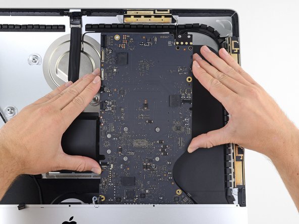
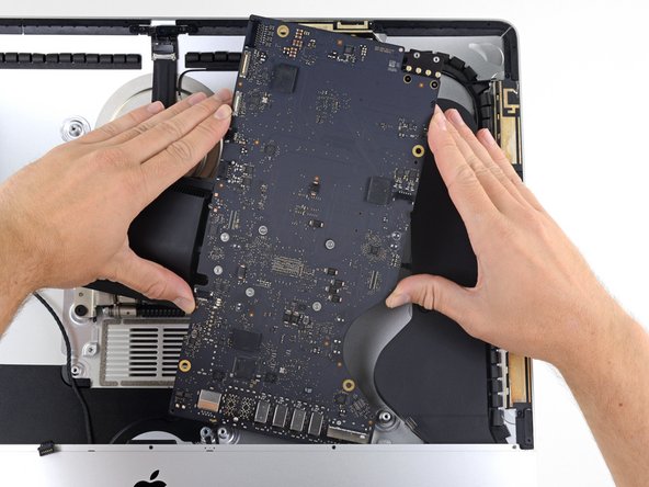
Tilt the top of the logic board away from the rear enclosure.
-
Lift the logic board straight up and out of the iMac.
-
-
Este passo não foi traduzido. Ajude a traduzi-lo
-
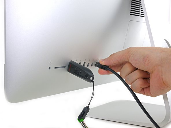
Use a USB flash drive and/or ethernet cable to ensure the logic board is aligned correctly while you screw it in.
-
-
Este passo não foi traduzido. Ajude a traduzi-lo
-
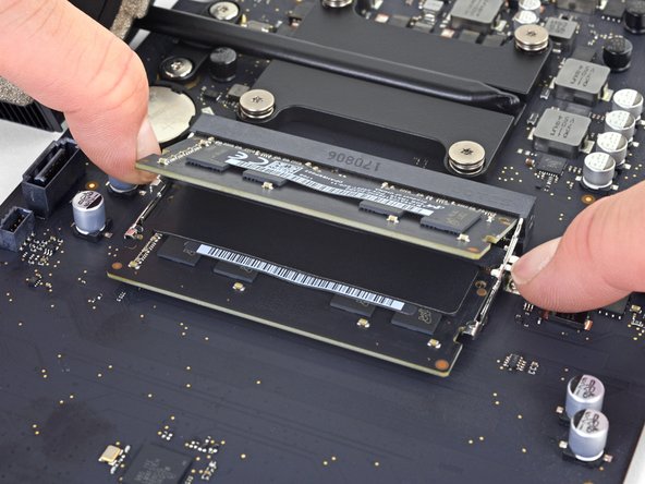
Handling the board by the edges, flip the logic board over to access the two RAM modules.
-
Two clips secure the RAM module in place, one on each side. Using your fingers, spread the clips away from the RAM module.
-
-
Este passo não foi traduzido. Ajude a traduzi-lo
-
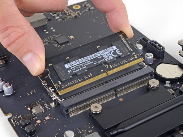
Lift the RAM module to an angle of about 30 degrees and slide it out.
-
-
Este passo não foi traduzido. Ajude a traduzi-lo
-
Peel off and transfer the thermal pad from the original RAM stick to your replacement RAM before you install it in the lower slot.
-


Cancelar: não concluí este guia.
28 outras pessoas executaram este guia.

9 comentários
Thought this was going to be extremely difficult but once I started with these instructions it actually wasn’t that bad, though it took me a slow and careful 3.5 hours. Was quite nervous handling that power supply though!
Excellent guide! It took me about 1.5 hours to complete the entire RAM+SSD installation. The iMac has massively improved and feels like a new computer: way way faster than before, with a 1TB Samsung SSD, 32GB of RAM and a brand new installation of macOS Catalina. Be very careful with the I/O ports, especially with the USB-C/Thunderbolt ones: the alignment is critical, as well as the correct position of the logic board in relation to the case. Even a slight misalignment can impede the USB-C plug from fully entering the port, making it hard or impossible to establish a connection.
Great guide… took a mediocre “unupgradable” iMac to 32 GB ram and new SSD HD (the other guide… but crosses with this). Excellent guidance. If you have to fix or upgrade anything else while changing out the RAM, this is the time and performed steps to do it with. Read the others to see the variations you need to do (like steps to clone the HD before changing, etc.) but as deep as you get into this machine, it exposes pretty much everything. Again, great work!
Wonderful guide! I was afraid that I am not going to make it since I don’t have a lot of experience in such things but following the steps carefully, paying attention to every detail, has led me to successfully upgrade my iMac 3086 with 1TB SSD and 32GB RAM. I was really afraid that this RAM upgrade probably won’t work because it’s been said on everymac.com that the maximum is 16GB and I’ve read somewhere about a person whose iMac didn’t even start after such intervention. I decided to purchase Crucial 2x16GB at 2400MHz, despite that the iMac has 2133Mhz bus. I trust this brand and I’ve already upgraded my MacBook Pro 15” mid-2012 with the same brand, again pushing the RAM beyond the official limits and it still works great. The SSD I put here is also from Crucial and I just turned on the iMac and it runs like never before! The whole procedure took me a bit over 2 hours. Thanks for the great work with this guide!!!
Hey Alex, I’m also worried about the compatibility of the Crucial RAM, so could you tell me which especific model did you use, please?