Ir para o conteúdo principal

Esta versão pode conter edições incorretas. Mude para o último instantâneo verificado.

Pré-requisito somente
Este guia destina-se apenas a ser usado como pré-requisito para outros guias. É incompleto por si só.

O que você precisa

  1. Este passo não foi traduzido. Ajude a traduzi-lo

    : passo 1, imagem 1 %32 : passo 1, imagem 2 %32
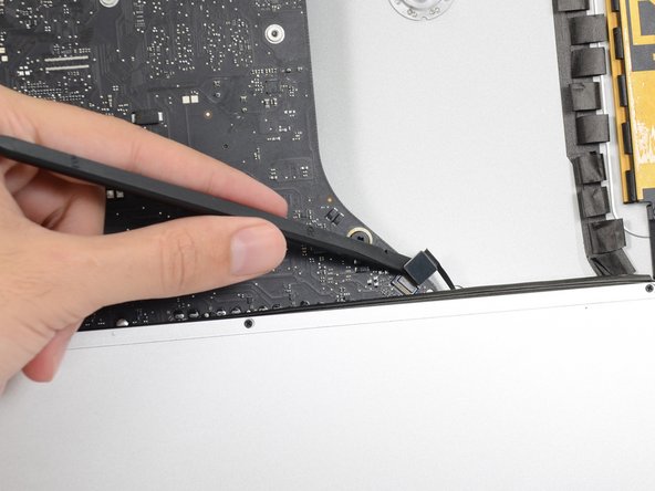
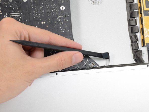
    • Push on each side of the left speaker cable connector with the tip of a spudger and gently walk it out of its socket.

  2. Este passo não foi traduzido. Ajude a traduzi-lo

    : passo 2, imagem 1 %32 : passo 2, imagem 2 %32
    Ferramenta utilizada nesse passo:
    Tweezers
    $4.99
    Comprar
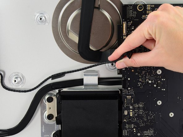
    • If necessary, use a pair of tweezers to gently peel the tape securing the left speaker cable to the SATA data/power cable.

    • This tape only needs to be removed if you are removing the left speaker.

  3. Este passo não foi traduzido. Ajude a traduzi-lo

    : passo 3, imagem 1 %32 : passo 3, imagem 2 %32 : passo 3, imagem 3 %32
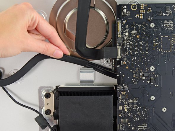
    • De-route the left speaker cable by pulling it straight up out of the retaining clip in the back of the rear enclosure.

    • In a similar fashion, lift the combo SATA data/power cable up out of the retaining clip.

  4. Este passo não foi traduzido. Ajude a traduzi-lo

    : passo 4, imagem 1 %32 : passo 4, imagem 2 %32 : passo 4, imagem 3 %32
    • Use the flat edge of a spudger to flip up the metal retaining bracket on the iSight camera cable connector.

    • Pull the iSight camera cable straight out of its socket on the logic board.

    • Do not use excessive force. This is a delicate connector that can be easily damaged.

  5. Este passo não foi traduzido. Ajude a traduzi-lo

    : passo 5, imagem 1 %32 : passo 5, imagem 2 %32 : passo 5, imagem 3 %32
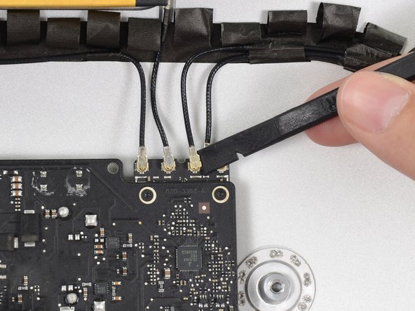
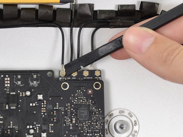
    • Use the flat edge of a spudger to disconnect each of the four antenna connectors from the AirPort/Bluetooth card.

    • Note the original positions for each connector when reconnecting the cables.

  6. Este passo não foi traduzido. Ajude a traduzi-lo

    : passo 6, imagem 1 %32 : passo 6, imagem 2 %32 : passo 6, imagem 3 %32
    • Use the flat edge of a spudger to pry the headphone jack cable connector from its socket on the logic board.

    • Push the cable slightly to the right to clear it for the removal of the logic board.

  7. Este passo não foi traduzido. Ajude a traduzi-lo

    : passo 7, imagem 1 %32
    • Remove the following screws securing the exhaust duct to the rear enclosure:

    • Two 6.3 mm T8 screws

    • Two 4.7 mm T8 screws

  8. Este passo não foi traduzido. Ajude a traduzi-lo

    : passo 8, imagem 1 %32
    • Remove the four 7.2 mm T10 screws securing the logic board to the rear enclosure.

  9. Este passo não foi traduzido. Ajude a traduzi-lo

    : passo 9, imagem 1 %32 : passo 9, imagem 2 %32 : passo 9, imagem 3 %32
    • Tilt the top of the logic board away from the rear enclosure.

    • Lift the logic board straight up and out of the iMac.

    • Be careful not to snag the board on any of the rear case's screw posts.

    • The I/O boards at the bottom of the logic board will be the greatest challenge. It is recommended to pull gently to avoid any damage.

  10. Este passo não foi traduzido. Ajude a traduzi-lo

    : passo 10, imagem 1 %32 : passo 10, imagem 2 %32
    • When installing the logic board, take care to align the exterior I/O ports correctly. The logic board can sit crooked even when secured with all its screws.

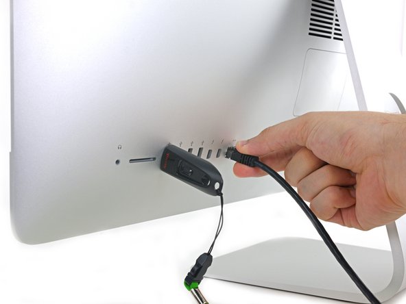
    • Use a USB flash drive and/or ethernet cable to ensure the logic board is seated correctly while you screw it in.

Linha de Chegada

Sam Goldheart

Membro desde: 10/18/12

465.970 Reputação

Autoria de 538 guias

Equipe

iFixit Membro de iFixit

Staff

Membros da 136

Autoria de 17.299 guias

0 comentários

Adicione um comentário

Exibir estatísticas:

Últimas 24 horas: 0

Últimos 7 dias: 3

Últimos 30 dias: 13

Duração total: 135