Esta versão pode conter edições incorretas. Mude para o último instantâneo verificado.
O que você precisa
-
-
-
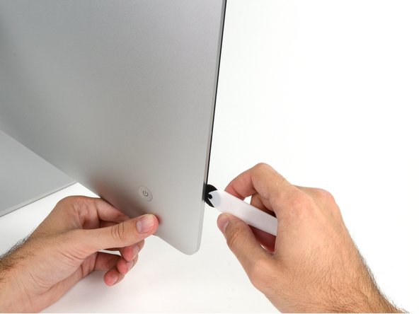
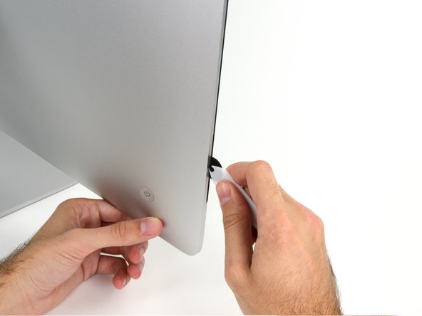
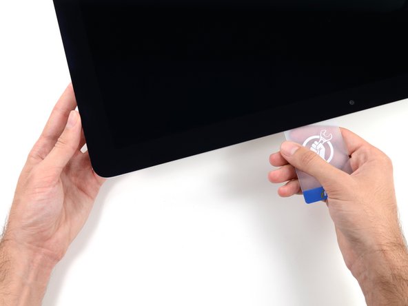
Começando pelo canto direito superior do iMac, force um cartão de plástico por entre a tela e a moldura.
-
-
-
Este passo não foi traduzido. Ajude a traduzi-lo
-
Remove the following five Phillips screws holding the lower support bracket in place:
-
Four 3.2 mm screws
-
One 1.7 mm screw
-
-
Este passo não foi traduzido. Ajude a traduzi-lo
-
Remove the lower support bracket from the iMac enclosure.
-
-
Este passo não foi traduzido. Ajude a traduzi-lo
-
Use a spudger to loosen the right speaker cable's connector from its socket on the logic board.
-
Pull the connector downwards to remove it from its socket.
-
-
Este passo não foi traduzido. Ajude a traduzi-lo
-
Remove the two 10.0 mm T10 screws securing the right speaker to the rear enclosure.
-
-
Este passo não foi traduzido. Ajude a traduzi-lo
-
Pull the top of the right speaker away from the rear enclosure, about half an inch, to expose the antenna cable running down its right side.
-
-
Este passo não foi traduzido. Ajude a traduzi-lo
-
Insert the tip of a spudger between the right speaker and the antenna cable that is routed into the speaker's right side.
-
Run the spudger down along the right side of the speaker to pry the antenna cable from its channel in the right speaker.
-
-
Este passo não foi traduzido. Ajude a traduzi-lo
-
Pull the right speaker straight up about an inch, toward the top of the iMac.
-
Lift the right speaker straight up and remove it from the iMac. This may take some force, both hands and rocking the speaker right and left to get it out.
-
-
-
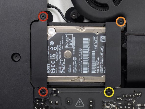
Remova os seguintes parafusos que fixam o suporte do disco rígido no invólucro traseiro:
-
dois parafusos Torx T10 de 21 mm do suporte esquerdo do disco rígido.
-
um parafuso Torx T10 de 9 mm.
-
um parafuso Torx T10 de 27 mm.
-
-
Este passo não foi traduzido. Ajude a traduzi-lo
-
Use the tip of a spudger to push each side of the power button cable connector and gently "walk" it out of its socket.
-
-
Este passo não foi traduzido. Ajude a traduzi-lo
-
Gently push upward on each side of the power supply control cable connector with the tip of a spudger to gently "walk" it out of its socket.
-
-
Este passo não foi traduzido. Ajude a traduzi-lo
-
Remove the two 7.2 mm T10 screws securing the power supply to the rear enclosure.
-
-
Este passo não foi traduzido. Ajude a traduzi-lo
-
Pull the power supply slightly up and out from the rear enclosure.
-
Rotate the power supply counterclockwise, lifting the right side up about an inch higher than the left.
-
-
Este passo não foi traduzido. Ajude a traduzi-lo
-
Slide the power supply to the right to clear the screw posts on the rear enclosure.
-
-
Este passo não foi traduzido. Ajude a traduzi-lo
-
Rock the power supply forward and remove it from its recess in the rear enclosure.
-
-
Este passo não foi traduzido. Ajude a traduzi-lo
-
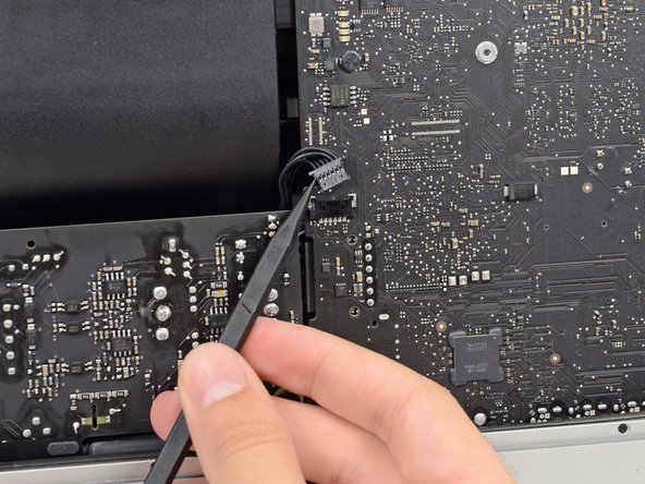
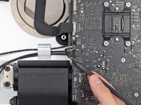
Squeeze the DC power cable connector tab and pull it straight out of its socket on the back of the logic board.
-
-
Este passo não foi traduzido. Ajude a traduzi-lo
-
Use the flat end of a spudger to push the clip on the side of the AC inlet cable connector inward.
-
While holding on the release clip with the spudger, grasp the AC inlet cable, and pull the connector straight out of its socket.
-
-
Este passo não foi traduzido. Ajude a traduzi-lo
-
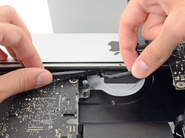
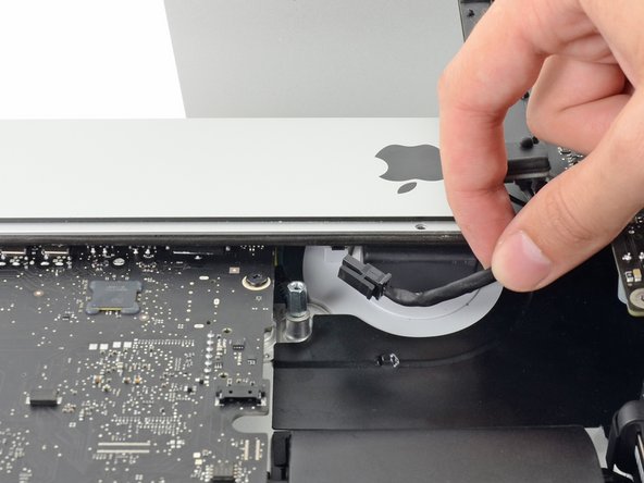
Gently pull the fan cable connector straight away from its socket on the logic board.
-
-
Este passo não foi traduzido. Ajude a traduzi-lo
-
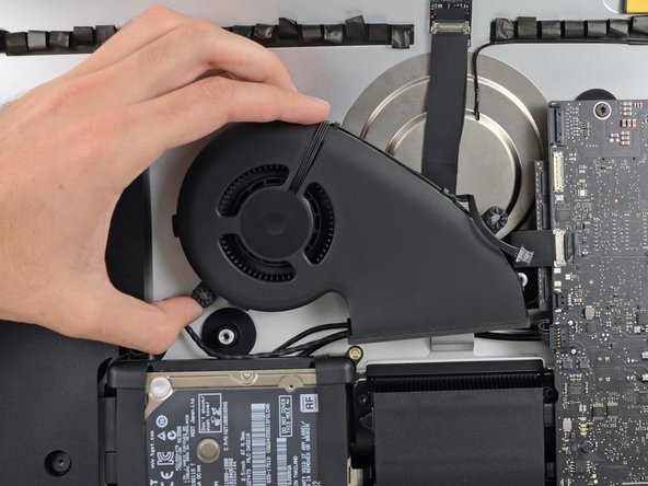
Remove the three 12.3 mm T10 shoulder screws securing the fan to the rear enclosure.
-
-
Este passo não foi traduzido. Ajude a traduzi-lo
-
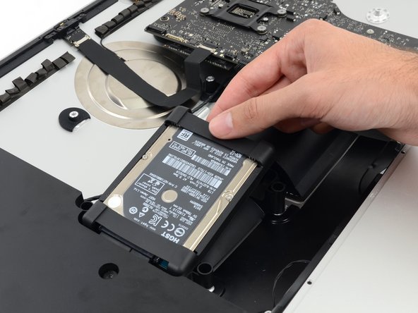
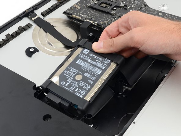
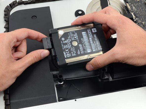
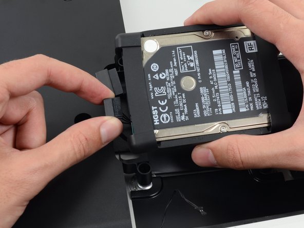
Lift the hard drive from the edge nearest the logic board and pull it slightly out of its recess.
-
-
Este passo não foi traduzido. Ajude a traduzi-lo
-
Remove the single 7.2 mm T10 screw securing the hard drive tray to the rear enclosure.
-
-
Este passo não foi traduzido. Ajude a traduzi-lo
-
Remove the hard drive tray from the rear enclosure.
-
-
Este passo não foi traduzido. Ajude a traduzi-lo
-
Push on each side of the left speaker cable connector with the tip of a spudger and gently "walk" it out of its socket.
-
-
Este passo não foi traduzido. Ajude a traduzi-lo
-
De-route the left speaker cable by pulling it straight up out of the retaining clip in the back of the rear enclosure.
-
-
Este passo não foi traduzido. Ajude a traduzi-lo
-
In a similar fashion as the previous step, de-route the SATA data and power cables up out of the retaining clip.
-
-
Este passo não foi traduzido. Ajude a traduzi-lo
-
Use the flat edge of a spudger to flip up the metal retaining bracket on the iSight camera cable connector.
-
Pull the iSight camera cable straight out of its socket on the logic board.
-
-
Este passo não foi traduzido. Ajude a traduzi-lo
-
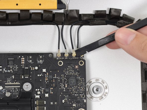
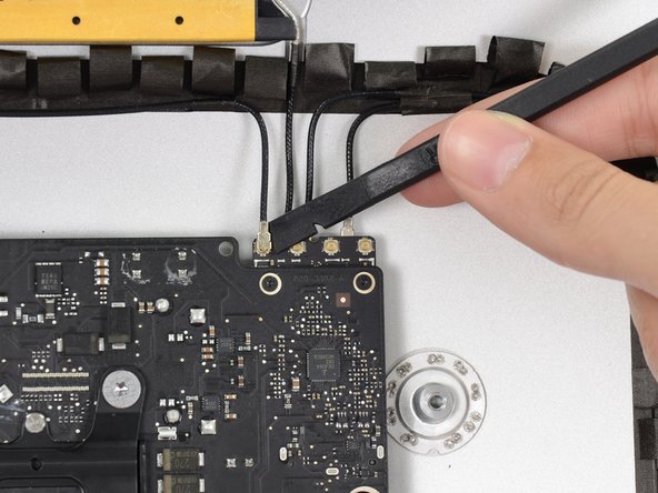
Use the flat edge of a spudger to disconnect each of the four antenna connectors from the AirPort/Bluetooth card.
-
-
Este passo não foi traduzido. Ajude a traduzi-lo
-
If brackets secure the four antenna cables, remove the two T5 Torx screws from the brackets.
-
-
Este passo não foi traduzido. Ajude a traduzi-lo
-
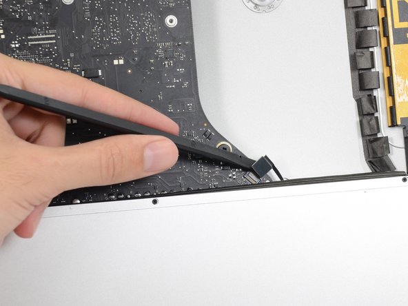
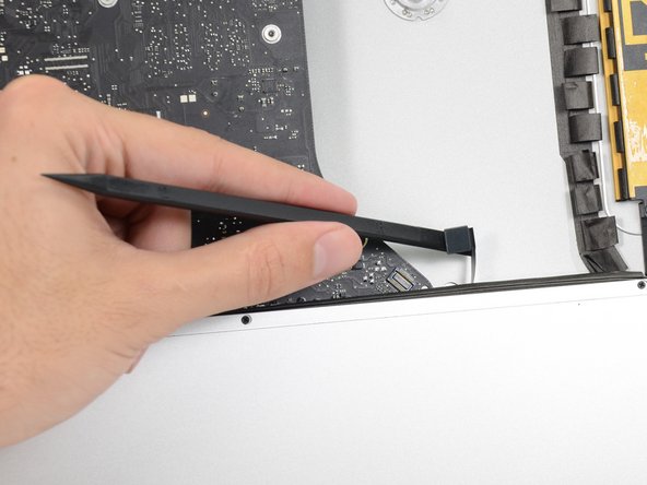
Use the flat edge of a spudger to pry the headphone jack cable connector from its socket on the logic board.
-
-
Este passo não foi traduzido. Ajude a traduzi-lo
-
Remove the following screws securing the exhaust duct to the rear enclosure:
-
Two 6.3 mm T8 screws
-
Two 4.7 mm T8 screws
-
-
Este passo não foi traduzido. Ajude a traduzi-lo
-
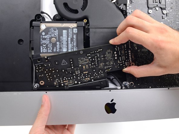
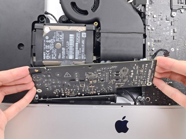
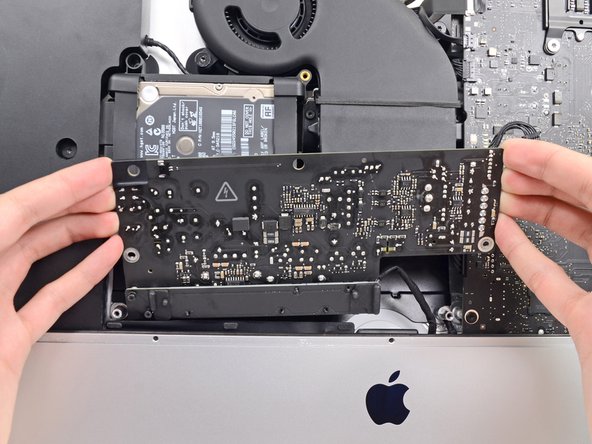
Remove the four 7.2 mm T10 screws securing the logic board to the rear enclosure.
-
-
Este passo não foi traduzido. Ajude a traduzi-lo
-
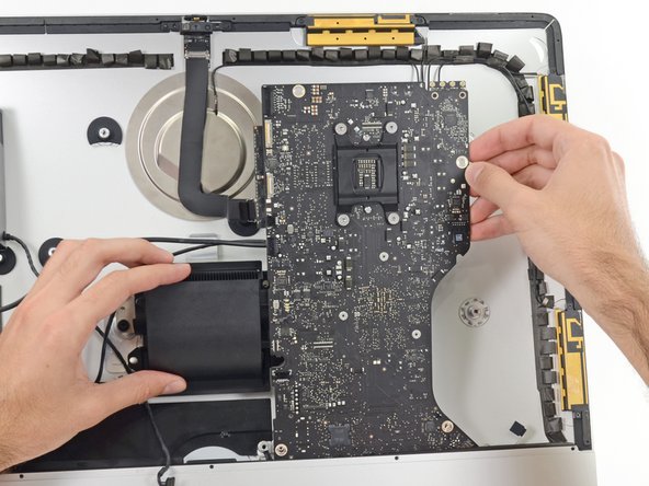
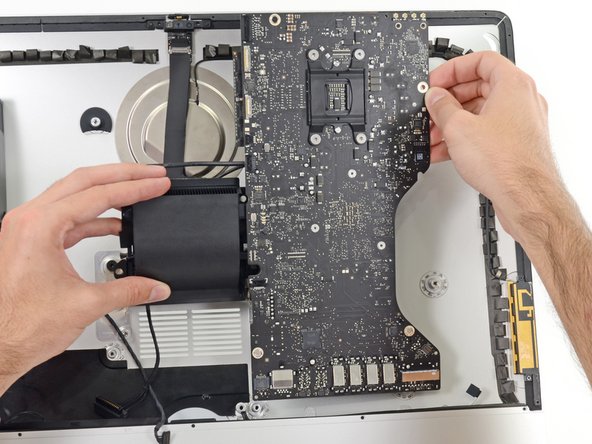
Tilt the top of the logic board away from the rear enclosure.
-
Lift the logic board straight up and out of the iMac.
-
-
Este passo não foi traduzido. Ajude a traduzi-lo
-
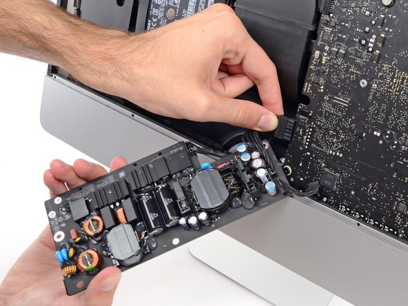
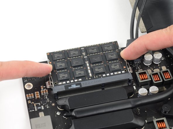
Release the tabs on each side of the RAM module by simultaneously pushing each tab away.
-
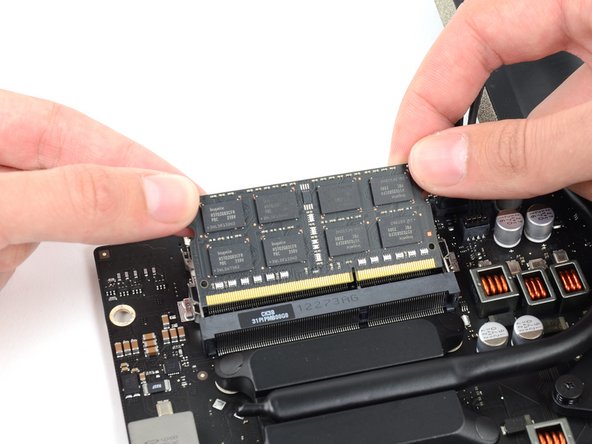
Grab the top left and right corners of the RAM module and carefully pull it straight out of its socket.
-


Cancelar: não concluí este guia.
135 outras pessoas executaram este guia.


18 comentários
I used the iMac Opening Tool just as shown starting in step 2 to separate the tape. DISASTER! The screen cracked! I used the tool slowly and carefully and despite this, the screen cracked. I should have simply used a guitar pick. That said, I decided to see if I could upgrade the 8GB RAM to 16GB RAM WITHOUT removing the logic board all performing all of these steps. I found I could simply remove the FAN assembly as shown in step 43. This makes enough room to reach behind the logic board and unclip the 2 memory modules. I installed 2 8GB modules (1600MHz DDR3L SO-DIMM PC12800 204 Pin) without much trouble. I used a plastic stick to reach behind the logic board and unclip the existing memory modules, then carefully inserted the new ones and clipped them into place. This is much easier than performing all of these steps.
Hi There, I am interested in going in and upgrading my RAM to 16. Did you do all the steps ups to 43? Remove the power supply? Did you remove the hard Drive? I take it you had to do step 53 as well and remove the iSight camera cable first? I may try it your way, I hate to have to unplug 98% of everything to do this. Thanks for the tip.
I added extra RAM by following step 1-23, then skipping to do just 41-43 and then reach the RAM from the back of the logic board. It was difficult to reach but possible.
Mikael -
Wow, thanks. That was much easier. I unscrewed the corner Torx screw holding the mobo down for just a touch of flex.
Used a couple of screw drivers to pull the tabs out
It helps if you have done a bunch of memory upgrades so you have a feel for how to get the chips in.
cyadmark -
Thanks for the tips here.I used a guitar pick and some credit cards as suggested, and to worked fine. I also followed Mikael’s suggestion :
“I added extra RAM by following step 1-23, then skipping to do just 41-43 and then reach the RAM from the back of the logic board. It was difficult to reach but possible.”
which worked fine for me too. Thanks for the suggestion. Have ordered tools & adhesive from ifixit anyway cos the site & its community showed me how to do it all anyway