Esta versão pode conter edições incorretas. Mude para o último instantâneo verificado.
O que você precisa
-
Este passo não foi traduzido. Ajude a traduzi-lo
-
In the proceeding steps, you will disconnect the following cables:
-
SD Board
-
Left/Right Speaker and Microphone
-
Audio Port
-
Wi-Fi Antenna
-
Right Temperature Sensor, Bluetooth/Ambient Light Sensor/Camera/Left Temperature, and Hard Drive Fan
-
CPU Fan/Ambient Temperature and Power Button
-
IR Sensor
-
-
Este passo não foi traduzido. Ajude a traduzi-lo
-
Pull the SD board cable out of its socket on the logic board.
-
-
Este passo não foi traduzido. Ajude a traduzi-lo
-
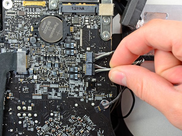
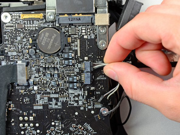
Disconnect the microphone, left speaker, and right speaker cables by pulling their connectors toward the right side of the iMac.
-
-
Este passo não foi traduzido. Ajude a traduzi-lo
-
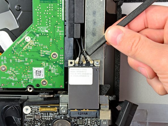
Use the flat end of a spudger to pry all three AirPort antenna connectors up from their sockets on the AirPort board.
-
-
Este passo não foi traduzido. Ajude a traduzi-lo
-
Pull the hard drive fan connector toward the top edge of the iMac to disconnect it from its socket on the logic board.
-
-
Este passo não foi traduzido. Ajude a traduzi-lo
-
Use your thumbnails on both sides of the Bluetooth/ambient light sensor/camera/left temperature connector to push it toward the top edge of the iMac and out of its socket on the logic board.
-
-
-
Este passo não foi traduzido. Ajude a traduzi-lo
-
Use your thumbnails to push the right temperature sensor connector toward the top edge of the iMac and out of its socket.
-
-
Este passo não foi traduzido. Ajude a traduzi-lo
-
Pull the CPU fan/ambient temperature sensor connector toward the bottom left edge of the iMac and out of its socket on the logic board.
-
-
Este passo não foi traduzido. Ajude a traduzi-lo
-
Pull the power button connector toward the bottom left corner of the iMac to disconnect it from its socket on the logic board.
-
-
Este passo não foi traduzido. Ajude a traduzi-lo
-
Use your thumbs to push the IR sensor connector toward the top edge of the iMac and out of its socket on the logic board.
-
Pull the IR sensor board up from behind the front face of the outer case.
-
Remove the IR sensor and set it aside.
-
-
Este passo não foi traduzido. Ajude a traduzi-lo
-
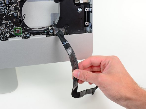
Pull the audio port cable connector toward the left side of the iMac to disconnect it from the logic board.
-
Peel the audio port cable off the front face of the logic board and let it hang down as shown in the second picture.
-
-
Este passo não foi traduzido. Ajude a traduzi-lo
-
Remove the following seven screws:
-
Two 7 mm T10 torx screws
-
One 30 mm T10 Torx screw
-
Two 25 mm T10 Torx screws
-
Two 21 mm T10 Torx screws
-
-
Este passo não foi traduzido. Ajude a traduzi-lo
-
Remove the following four screws from the power supply:
-
One 9.3 mm T10 coarse-threaded screw
-
One 25 mm T10 coarse-threaded screw
-
Two 22 mm fine-threaded screws
-
Pull the upper right and lower left corners of the power supply away from the rear case to dislodge the mounting posts attached to the power supply's corners.
-
-
Este passo não foi traduzido. Ajude a traduzi-lo
-
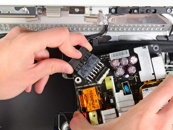
Carefully lift the power supply out of the outer case and rotate it to expose the cable lock as shown, minding the DC-out and AC-in cables still attaching it to the iMac.
-
Disconnect the DC-out cable by depressing the locking mechanism on the connector while you pull the connector away from its socket on the power supply.
-
Once the locking mechanism has cleared the socket, pull the DC-in connector away from the power supply.
-
-
Este passo não foi traduzido. Ajude a traduzi-lo
-
Disconnect the AC-In cable by depressing the locking mechanism while pulling the connector away from its socket.
-
Remove the power supply from the outer case.
-
-
Este passo não foi traduzido. Ajude a traduzi-lo
-
Remove the plastic wall that is installed directly to the right of the LED driver board.
-
-
Este passo não foi traduzido. Ajude a traduzi-lo
-
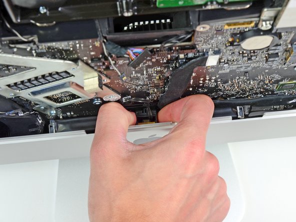
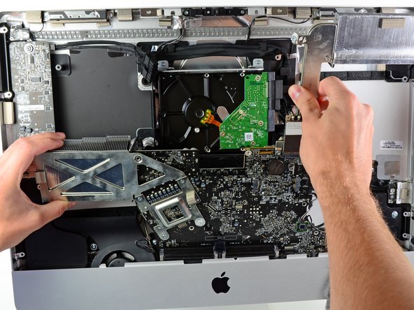
Slightly pull the logic board away from the back of the outer case, then lift it upward to clear the lower front face of the outer case.
-


Cancelar: não concluí este guia.
Uma outra pessoa concluiu este guia.
