Esta versão pode conter edições incorretas. Mude para o último instantâneo verificado.
O que você precisa
-
Este passo não foi traduzido. Ajude a traduzi-lo
-
Loosen the two Phillips screws securing the access door to your iMac.
-
-
Este passo não foi traduzido. Ajude a traduzi-lo
-
Remove the three T8 Torx screws securing the front bezel to the rear panel.
-
-
Este passo não foi traduzido. Ajude a traduzi-lo
-
Use your thumbs to press both RAM arms in past the front bezel for enough clearance to lift it off the rear case.
-
-
Este passo não foi traduzido. Ajude a traduzi-lo
-
While holding the RAM arms in with your thumbs, lift the lower edge of the front bezel enough to clear the rear case.
-
-
Este passo não foi traduzido. Ajude a traduzi-lo
-
Insert a plastic card up into the corner of the air vent slot at the top of the rear case.
-
Push the card toward the top of the iMac to release the front bezel latch.
-
Pull the front bezel away from the rear case.
-
Repeat this process for the other side of the front bezel.
-
-
Este passo não foi traduzido. Ajude a traduzi-lo
-
Lay your iMac stand-side down on a table.
-
Lift the front bezel from its lower edge and rotate it away from the rest of your iMac, minding the RAM arms that may get caught.
-
Lay the front bezel above the rest of the iMac.
-
-
Este passo não foi traduzido. Ajude a traduzi-lo
-
If necessary, remove the piece of kapton tape wrapped around the microphone and camera cables.
-
-
Este passo não foi traduzido. Ajude a traduzi-lo
-
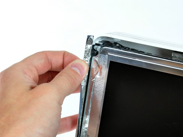
Peel back the aluminum EMI shield up off the lower three edges of the rear case.
-
-
Este passo não foi traduzido. Ajude a traduzi-lo
-
Remove the two 5 mm T6 Torx screws securing the display data cable to the logic board.
-
Using its attached black tab, pull the display data cable connector up off the logic board.
-
-
-
Este passo não foi traduzido. Ajude a traduzi-lo
-
Pull the inverter cable connector up off its socket on the logic board.
-
-
Este passo não foi traduzido. Ajude a traduzi-lo
-
Peel back the aluminum EMI tape from the two vertical edges of the display.
-
-
Este passo não foi traduzido. Ajude a traduzi-lo
-
Remove the four recessed coarse-thread 7.5 mm T10 Torx screws securing the display to the rear case.
-
-
Este passo não foi traduzido. Ajude a traduzi-lo
-
Lift the display from its lower edge and pull it toward yourself to peel it off the EMI shield attached to its top edge.
-
-
Este passo não foi traduzido. Ajude a traduzi-lo
-
Remove the T10 Torx screw securing the optical drive flex cable mounting bracket to the logic board.
-
Remove the flex cable mounting bracket.
-
-
Este passo não foi traduzido. Ajude a traduzi-lo
-
Lift the optical drive flex cable connector straight up off the logic board.
-
-
Este passo não foi traduzido. Ajude a traduzi-lo
-
Move the SATA data cable away from the edge of the optical drive.
-
-
Este passo não foi traduzido. Ajude a traduzi-lo
-
Insert the flat end of a spudger into the gap between the optical drive and its bracket until it contacts the chassis.
-
Grab the spudger as close to the surface of the optical drive as you can, then depress the release tab with your thumb while pulling toward yourself.
-
-
Este passo não foi traduzido. Ajude a traduzi-lo
-
Remove the two T10 Torx screws from the side of the optical drive.
-
-
Este passo não foi traduzido. Ajude a traduzi-lo
-
Use the flat end of a spudger to press the bottom edge of the lower optical drive bracket release tab toward the lower edge of the iMac.
-
Maneuver the optical drive out of the rear case, minding the two plastic pins molded into the rear case near the open end of the optical drive that can break off.
-
-
Este passo não foi traduzido. Ajude a traduzi-lo
-
Remove the two T10 Torx screws from the side of your optical drive.
-
-
Este passo não foi traduzido. Ajude a traduzi-lo
-
Push the two optical drive bracket tabs out of their slots in the top of the optical drive.
-
-
Este passo não foi traduzido. Ajude a traduzi-lo
-
Using the tip of a spudger, press the optical drive bracket tab out of its slot on the side of the optical drive.
-
-
Este passo não foi traduzido. Ajude a traduzi-lo
-
Use the tip of a spudger to push the optical drive bracket tabs out of their slots on the bottom of the optical drive.
-
-
Este passo não foi traduzido. Ajude a traduzi-lo
-
Pull the optical drive bracket toward the open end of the optical drive to free it from the optical drive.
-
-
Este passo não foi traduzido. Ajude a traduzi-lo
-
Remove the two T6 Torx screws securing the optical drive flex cable to the optical drive.
-
-
Este passo não foi traduzido. Ajude a traduzi-lo
-
Insert the flat end of a spudger into the gap between the optical drive flex cable connector and the optical drive.
-
Twist the spudger to separate the connector from the optical drive.
-
-
Este passo não foi traduzido. Ajude a traduzi-lo
-
Pull the optical drive flex cable connector away from the optical drive.
-
-
Este passo não foi traduzido. Ajude a traduzi-lo
-
Use a spudger to pry the optical drive thermal sensor off the optical drive.
-
-
Este passo não foi traduzido. Ajude a traduzi-lo
-
Use the flat end of a spudger to remove the small piece of EMI foam from the underside of the optical drive.
-


Cancelar: não concluí este guia.
7 outras pessoas executaram este guia.

Um comentário
Excellent information that is timely for me because I need to replace my hard disk. Do you recall the name of the hard disk you used to replace the original, just quickly?