Esta versão pode conter edições incorretas. Mude para o último instantâneo verificado.
O que você precisa
-
Este passo não foi traduzido. Ajude a traduzi-lo
-
Unplug all the cables from the computer, including the power cable. Lay the computer face-down, supporting the neck and base with a soft cloth under the screen.
-
-
Este passo não foi traduzido. Ajude a traduzi-lo
-
Open the housing plate.
-
A fixed plug connector between the logic board and upper unit will cause some resistance. Pull gently but firmly.
-
-
-
Este passo não foi traduzido. Ajude a traduzi-lo
-
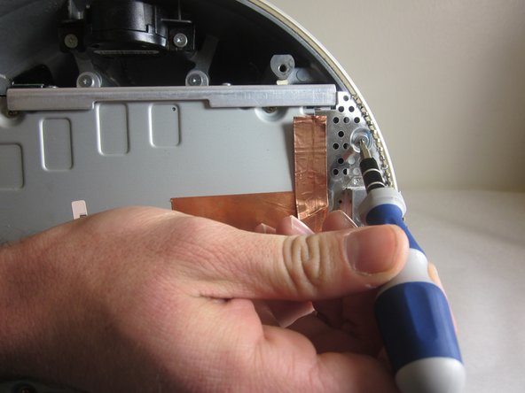
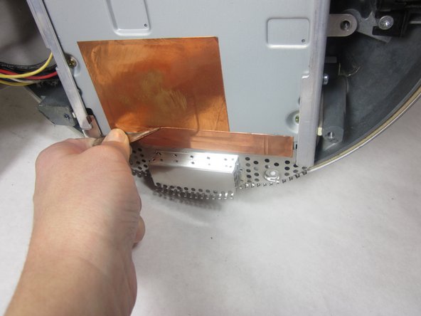
Remove the 2 torx 10mm screws on the EMI shield
-
Carefully remove shield and copper tape
-
-
Este passo não foi traduzido. Ajude a traduzi-lo
-
Remove the 4 10mm torx screws attatched to the drive carrier.
-
-
Este passo não foi traduzido. Ajude a traduzi-lo
-
Grasp the carrier with both hands on each side.
-
Remove the carrier by lifting up and out.
-
-
Este passo não foi traduzido. Ajude a traduzi-lo
-
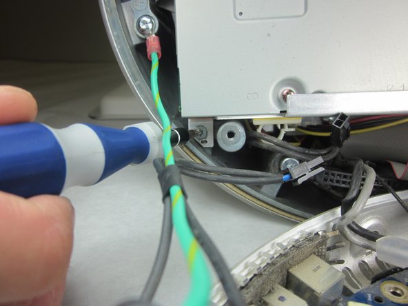
Flip the removed carrier to the right and pull out power cables.
-
-
Este passo não foi traduzido. Ajude a traduzi-lo
-
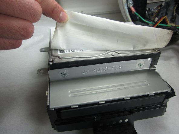
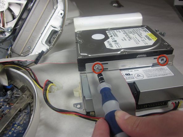
Peel back the white paper, revealing the screws that connect the hard drive to the carrier.
-
Remove the 4 T-10 5mm screws connecting the hard drive and frame. (There are 2 screws on each side)
-
-
Este passo não foi traduzido. Ajude a traduzi-lo
-
Slide the hard drive out from the frame and optical drive.
-
-
Este passo não foi traduzido. Ajude a traduzi-lo
-
Before you reassemble the computer, double check that your new hard drive has the same jumper configuration as the old one. This ensures the IDE "Master-Slave" protocol isn't interrupted. Some systems do not require this, but if you are having issues booting up afterwards with the storage or the disc drive, this could be the source of the problem.
-
-
Este passo não foi traduzido. Ajude a traduzi-lo
-
Remove the four T-10 6mm screws at the sides of the drive.
-


Cancelar: não concluí este guia.
7 outras pessoas executaram este guia.
Equipe

Cal Poly, Team 21-22, Maness Fall 2011 Membro de Cal Poly, Team 21-22, Maness Fall 2011
CPSU-MANESS-F11S21G22
Membros da 4
Autoria de 13 guias
2 comentários
Should step ten of removing the optical drive be broken into two different steps
Which brands/models should one use to replace a faulty optical drive in one of these iMac G4’s?