Esta versão pode conter edições incorretas. Mude para o último instantâneo verificado.
O que você precisa
-
Este passo não foi traduzido. Ajude a traduzi-lo
-
Use a coin to rotate the battery locking screw 90 degrees clockwise.
-
-
Este passo não foi traduzido. Ajude a traduzi-lo
-
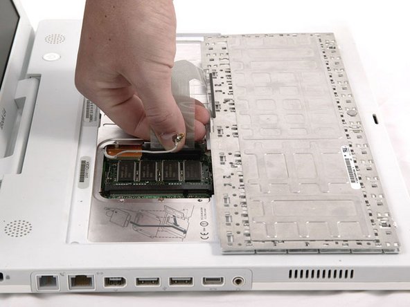
Pull the keyboard release tabs toward you and lift up on the keyboard until it pops free.
-
Flip the keyboard over, away from the screen, and rest it face-down on the trackpad area.
-
-
Este passo não foi traduzido. Ajude a traduzi-lo
-
Push the wire clasp away from the AirPort card and toward the display, then rotate up to free it from the RAM shield.
-
-
-
Este passo não foi traduzido. Ajude a traduzi-lo
-
Grasp the clear plastic tab on the AirPort card and pull toward the display.
-
-
Este passo não foi traduzido. Ajude a traduzi-lo
-
Hold the AirPort card in one hand and use your other hand to remove the antenna cable.
-
-
Este passo não foi traduzido. Ajude a traduzi-lo
-
Remove the four silver Phillips screws that secure the RAM shield.
-
-
Este passo não foi traduzido. Ajude a traduzi-lo
-
Grasp the metal bracket on top of the RAM shield and pull upward to remove the shield.
-
-
Este passo não foi traduzido. Ajude a traduzi-lo
-
Pull the keyboard cable up from the logic board, holding the cable as close to the connector as possible.
-
-
Este passo não foi traduzido. Ajude a traduzi-lo
-
Release the tabs on each side of the RAM chip at the same time. These tabs lock the chip in place and releasing them will cause the chip to "pop" up.
-


Cancelar: não concluí este guia.
32 outras pessoas executaram este guia.
