Introdução
Tripped over your power cord? At least you don't have to replace the entire logic board.
O que você precisa
-
-
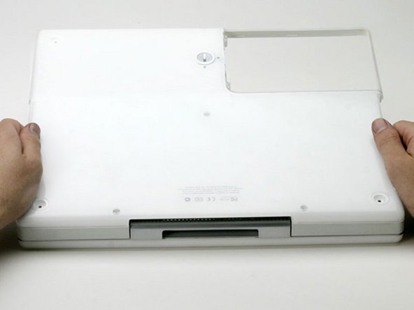
Use a coin to rotate the battery locking screw 90 degrees clockwise.
-
Lift the battery out of the computer.
 Pergunte ao FixBot
-
-
-
Pull the keyboard release tabs (highlighted in red) toward you and lift up on the keyboard until it pops free.
-
If the keyboard does not come free, use a small flathead screwdriver to turn the keyboard locking screw 180 degrees in either direction and try again.
-
Flip the keyboard over, away from the screen, and rest it face-down on the trackpad area.
-
-
-
Push the wire clasp toward the AirPort card and pull it up to free it from the RAM shield.
-
-
-
Grasp the clear plastic tab on the AirPort card and pull toward the right.
-
-
-
Hold the AirPort card in one hand and use your other hand to remove the antenna cable.
-
-
-
Grasp the metal bracket on top of the RAM shield and pull upward to remove the shield.
-
-
-
Pull the keyboard cable up from the logic board, holding the cable as close to the connector as possible.
-
-
-
Use a pin to remove the three rubber feet from the lower case.
-
-
-
Use a spudger or small flathead screwdriver to pry up the three metal rings that housed the rubber bumpers.
-
-
-
-
Remove the two Phillips screws on either side of the battery contacts.
-
-
-
Push the thin rims of the lower case surrounding the battery compartment in, bending them past the tabs, and then lift up to free that corner of the lower case.
-
-
-
Use a small flathead screwdriver to pry out the slot's lower rim and pull up on the lower case to free the slot from the tabs holding it.
-
-
-
Run a spudger along the seam between the lower case and upper case on the front of the computer to free the tabs locking the lower case.
-
Pull up on the lower case and continue to use the spudger as necessary until you hear three distinct clicks.
-
-
-
Once the front and sides of the lower case are free, turn the computer so that the back is facing you.
-
Pull the lower case up and toward you until the back tabs pop free.
-
-
-
Remove the small greasy springs with white plastic caps from either side of the battery contacts.
-
-
-
Remove the following 9 screws on the bottom of the computer:
-
Three 3 mm Phillips around the battery compartment.
-
Three 5 mm Phillips on the left and bottom edges.
-
Three 14.5 mm Phillips on the top and right edges (you may have to peel back the foil tape to reveal the screw near the security lock slot).
-
-
-
Turn over the computer and open it.
-
Pry up the magnet covering a Phillips screw near the middle of the computer.
-
-
-
Remove the following 3 screws on the edges of the keyboard area:
-
Two 6 mm Phillips underneath the keyboard area.
-
One 9 mm Phillips above the keyboard area.
-
-
-
With your fingernails, grasp the locking bar on either side and pull up a small amount (about 1/16" or 2 mm).
-
After disengaging the locking bar, slide the cable out of the connector.
-
-
-
Loosen the trackpad connector by pulling the top piece up slightly, freeing the trackpad ribbon.
-
Slide the orange trackpad ribbon out of the connector.
-
-
-
Use a straightened paperclip to open the optical drive tray, and pull it out about halfway.
-
-
-
Lift the upper case from the left side and use your other hand to pull out the right side in order to clear the power receptacle.
-
-
-
Lift the upper case enough to disconnect the blue and white power cable from the logic board.
-
Using your fingernails or a dental pick, carefully pry the connector from its socket.
-
-
-
Lift the upper case off completely and disconnect the red and black speaker cable from the logic board.
-
-
-
Remove the following 10 screws:
-
One 5 mm Phillips at the upper, right corner of the battery compartment.
-
Nine 6 mm Phillips scattered around the shield.
-
Lift the bottom shield off.
-
-
-
Remove the yellow tape securing the DC cable to the metal framework and disconnect the DC cable from the logic board.
-
-
-
Remove the single Phillips screw from the DC-In board.
-
Pull the DC-In board out of the computer, pulling the DC cable through the convenient slot beneath the board.
-


To reassemble your device, follow these instructions in reverse order.
Cancelar: não concluí este guia.
2 outras pessoas executaram este guia.
Documentos anexados
