Esta versão pode conter edições incorretas. Mude para o último instantâneo verificado.
O que você precisa
-
Este passo não foi traduzido. Ajude a traduzi-lo
-
Before you begin, switch off your phone.
-
Apply a heated iOpener to the rear glass to loosen the adhesive beneath the edges. Apply the iOpener for at least two minutes.
-
-
Este passo não foi traduzido. Ajude a traduzi-lo
-
Secure a suction handle to the lower edge of the rear glass, as close to the edge as possible.
-
Lift the rear glass with the suction handle to create a gap between the glass and the frame.
-
Insert an opening pick into the gap.
-
Slide the opening pick to the bottom right corner of the phone.
-
-
Este passo não foi traduzido. Ajude a traduzi-lo
-
Insert a second opening pick and slide it to the bottom left corner to cut the adhesive.
-
Leave the opening picks in place to prevent the adhesive from resealing.
-
-
Este passo não foi traduzido. Ajude a traduzi-lo
-
Insert a third opening pick at the bottom left corner.
-
Start to slide the opening pick from the bottom left corner along the side of the Xiaomi Mi 9 to cut the adhesive.
-
Leave the opening pick in the top left corner to prevent the adhesive from resealing.
-
-
Este passo não foi traduzido. Ajude a traduzi-lo
-
Insert a fourth opening pick under the top left corner of the rear glass.
-
Slide the opening pick along the top to cut the adhesive.
-
Leave the opening pick in the top right corner to prevent the adhesive from resealing.
-
-
-
Este passo não foi traduzido. Ajude a traduzi-lo
-
Insert a fifth opening pick at the top right corner of the phone.
-
Slide the opening pick along the right edge to cut the remaining adhesive.
-
-
Este passo não foi traduzido. Ajude a traduzi-lo
-
Remove the ten Phillips #00 screws (3 mm length) that secure the motherboard cover.
-
-
Este passo não foi traduzido. Ajude a traduzi-lo
-
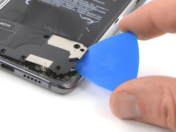
Insert an opening pick at the top right corner of the motherboard cover.
-
Twist the opening pick sideways to pry up and slightly lift the motherboard cover.
-
-
Este passo não foi traduzido. Ajude a traduzi-lo
-
Carefully remove the motherboard cover including the charging coil / NFC antenna.
-
-
Este passo não foi traduzido. Ajude a traduzi-lo
-
Use a spudger to pry up and disconnect the battery flex cable.
-
-
Este passo não foi traduzido. Ajude a traduzi-lo
-
Remove the seven Phillips #00 screws securing the loudspeaker unit:
-
Four silver 3.2 mm long screws
-
Two yellowish 3.8 mm long screws
-
One black 2.8 mm long screw
-
-
Este passo não foi traduzido. Ajude a traduzi-lo
-
Slide an opening pick under the right side of the loudspeaker unit.
-
Twist the opening pick sideways to pry up the loudspeaker unit until you can get a good grip.
-
-
Este passo não foi traduzido. Ajude a traduzi-lo
-
Carefully lift the loudspeaker unit and hinge it open towards the left side.
-
-
Este passo não foi traduzido. Ajude a traduzi-lo
-
Use a pair of tweezers to pry off and disconnect the antenna cable from the loudspeaker unit.
-
Remove the loudspeaker unit.
-


Cancelar: não concluí este guia.
4 outras pessoas executaram este guia.

