Esta versão pode conter edições incorretas. Mude para o último instantâneo verificado.
O que você precisa
-
Este passo não foi traduzido. Ajude a traduzi-lo
-
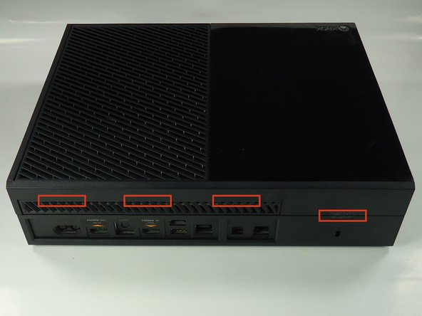
With a plastic opening tool, pry the side vent from the console.
-
-
Este passo não foi traduzido. Ajude a traduzi-lo
-
Slide the black angled tab behind the silver button toward the back of the console and set it aside.
-
-
Este passo não foi traduzido. Ajude a traduzi-lo
-
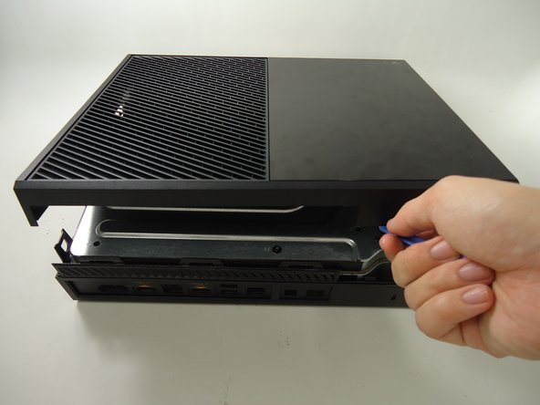
Use a plastic opening tool on the back to pry the top of the case from the bottom. Use an up and out motion to dislodge the clips. There are multiple clips to release on the back and two on the sides.
-
-
Este passo não foi traduzido. Ajude a traduzi-lo
-
Carefully lift the top of the case, note that there is a wire connecting the front panel to the motherboard. Take care not to break this.
-
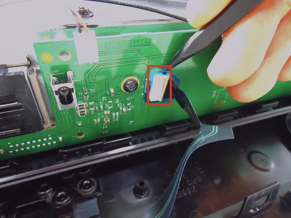
Using a spudger, release the ribbon wire from the front panel.
-
The top case is now free, set it aside.
-
-
-
Este passo não foi traduzido. Ajude a traduzi-lo
-
Remove the speaker by squeezing the the tab on the black plastic mounting piece and lifting it up.
-
Carefully unplug the connector from the green front panel board.
-
The speaker is now free, set it aside.
-
-
Este passo não foi traduzido. Ajude a traduzi-lo
-
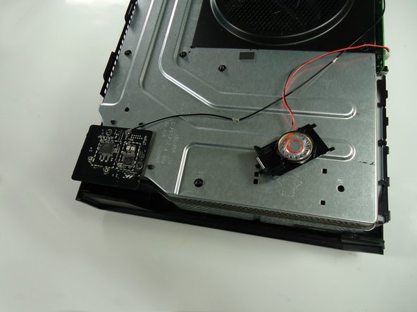
Unscrew the two 8.2mm T-9 screws securing the Wi-Fi board to the chassis.
-
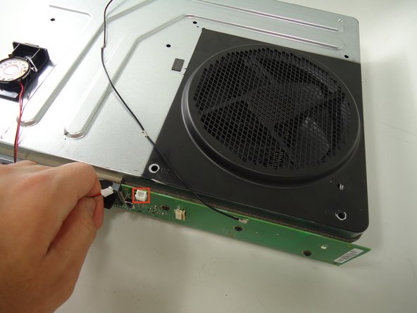
Using the spudger, gently lift the antenna connector from the Wi-Fi board.
-
-
Este passo não foi traduzido. Ajude a traduzi-lo
-
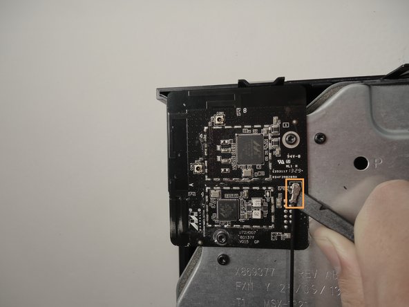
Using a spudger and a motion similar to the previous step, gently lift the antenna connector from the green board on the front.
-
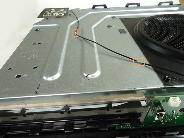
Carefully pull out the clips securing the antenna wire to the chassis, releasing the wire.
-
-
Este passo não foi traduzido. Ajude a traduzi-lo
-
Carefully pull the Wi-Fi board straight up to release it from the chassis. The Wi-Fi board is now free.
-
-
Este passo não foi traduzido. Ajude a traduzi-lo
-
Remove all eight of the 64.0 mm, T-9 screws labeled C1 through C8 securing the chassis top to the motherboard.
-
-
Este passo não foi traduzido. Ajude a traduzi-lo
-
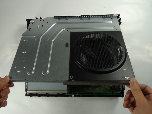
Lift the chassis top, being careful not to break the wire connecting the chassis top to the motherboard.
-
Unplug the connector labeled 3 on the motherboard by gently pulling up.
-
The chassis top is now free, set it aside.
-
-
Este passo não foi traduzido. Ajude a traduzi-lo
-
Lift the bottom half of the chassis (motherboard and all) from the bottom half of the black case.
-
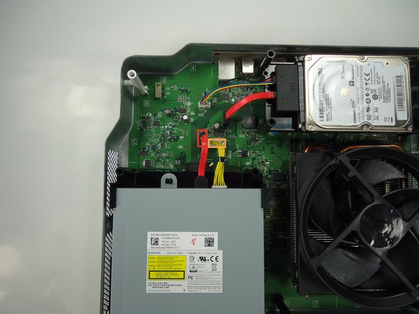
Unplug the red wire connecting the optical drive to the motherboard from its connector on the motherboard.
-
Unplug the yellow wire connecting the optical drive to the motherboard from its connector on the motherboard.
-
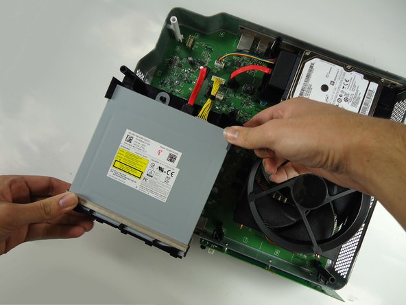
The optical drive is now free, lift it from the chassis and set it aside.
-


Cancelar: não concluí este guia.
16 outras pessoas executaram este guia.
Equipe

Cal Poly, Team 6-22, Maness Winter 2014 Membro de Cal Poly, Team 6-22, Maness Winter 2014
CPSU-MANESS-W14S6G22
Membros da 4
Autoria de 11 guias
7 comentários
Are the drives paired as the 360 ones were do we need to swap over the logic board to get game playback? Thanks
Yes they are married in the same way as the 360 is. It's not difficult at all to swap.
i cant do this im only a kid and my dad will get mad at me if I do this