Esta versão pode conter edições incorretas. Mude para o último instantâneo verificado.
O que você precisa
-
Este passo não foi traduzido. Ajude a traduzi-lo
-
Press the on/off button on the top to power the phone off.
-
-
Este passo não foi traduzido. Ajude a traduzi-lo
-
Remove the battery cover by pressing and sliding the cover down and off of the phone.
-
-
Este passo não foi traduzido. Ajude a traduzi-lo
-
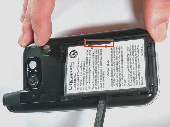
Pull the battery removal tab and lift the battery out of the phone.
-
-
Este passo não foi traduzido. Ajude a traduzi-lo
-
Remove the two 4.0-mm #000 Phillips screws at the top of the battery compartment. Tweezers may be useful to remove the screws.
-
-
Este passo não foi traduzido. Ajude a traduzi-lo
-
Use firm pressure to carefully pry off the cover with your fingers.
-
-
Este passo não foi traduzido. Ajude a traduzi-lo
-
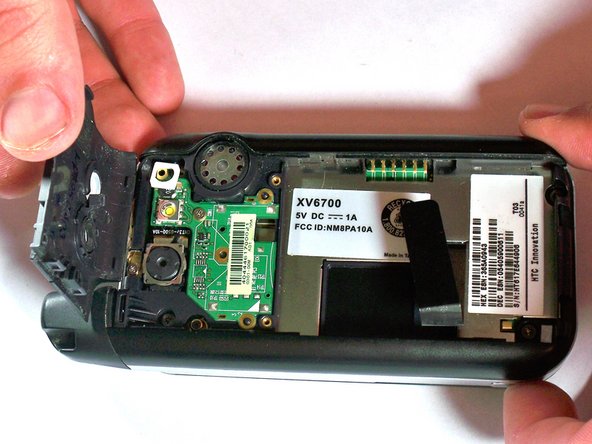
Remove the 4.0-mm #00 Phillips screw securing the camera flash circuit board. The board is still connected by a connector on the bottom of the board.
-
-
Este passo não foi traduzido. Ajude a traduzi-lo
-
Gently pry off the camera flash circuit board with the spudger.
-
-
-
Este passo não foi traduzido. Ajude a traduzi-lo
-
Remove the four 5.0-mm Torx T6 screws from the corners of the black cover.
-
-
Este passo não foi traduzido. Ajude a traduzi-lo
-
Remove the 4.0-mm #00 Phillips screw that holds the antenna in place. The antenna does not need to be removed.
-
-
Este passo não foi traduzido. Ajude a traduzi-lo
-
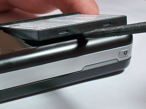
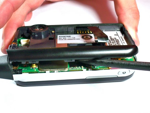
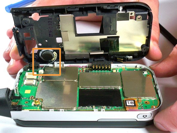
Use the spudger or plastic opening tools to apply firm but gentle pressure equally around the outside of the case.
-
Carefully pry the black portion of the case away from the silver portion.
-
-
Este passo não foi traduzido. Ajude a traduzi-lo
-
Using tweezers, pull with gentle pressure in the direction of the wire to unplug from the motherboard connector.
-
-
Este passo não foi traduzido. Ajude a traduzi-lo
-
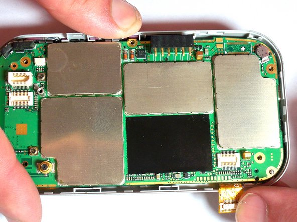
Remove the 4.0-mm #00 Phillips screw holding the motherboard in place. The screw is in the middle of the motherboard, near the outside edge.
-
-
Este passo não foi traduzido. Ajude a traduzi-lo
-
With your fingers, disconnect the keyboard cable from the motherboard. The cable is orange with the letters T/B printed on the connector.
-
-
Este passo não foi traduzido. Ajude a traduzi-lo
-
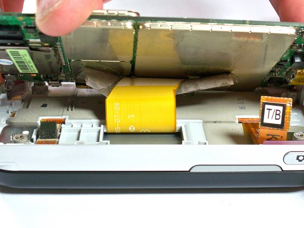
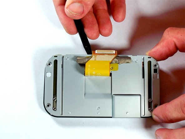
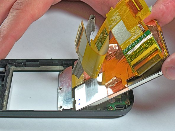
Carefully lift up on the motherboard with the spudger until you can see the display cable connected to the underside of the motherboard. The display cable connector will be taped over.
-
-
Este passo não foi traduzido. Ajude a traduzi-lo
-
Use the spudger to peel away the tape from the connector.
-
-
Este passo não foi traduzido. Ajude a traduzi-lo
-
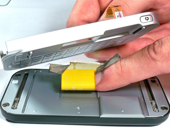
Using the spudger, pry away the display cable connector from the motherboard. The motherboard is now completely disconnected.
-
-
Este passo não foi traduzido. Ajude a traduzi-lo
-
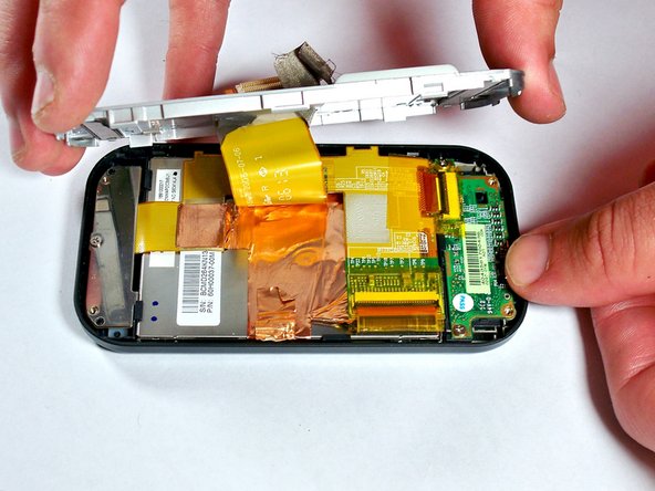
Remove the four 4.0-mm #00 Phillips screws that secure the slide-out keyboard to the screen enclosure.
-
-
Este passo não foi traduzido. Ajude a traduzi-lo
-
Carefully pull the display cable through the opening in the keyboard panel. The keyboard panel can then be set aside.
-
-
Este passo não foi traduzido. Ajude a traduzi-lo
-
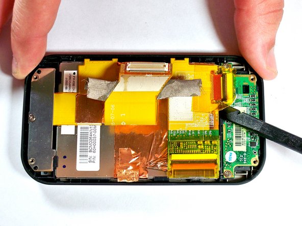
Remove four 5.0-mm Torx T6 screws from the screen enclosure.
-
-
Este passo não foi traduzido. Ajude a traduzi-lo
-
Pry the silver cover off the screen enclosure. The display cable should be pulled through the opening in the silver cover.
-
-
Este passo não foi traduzido. Ajude a traduzi-lo
-
Use the spudger to remove the tape from the connector between the screen and the front button circuit board.
-
Pry up on the brown connector to remove.
-
-
Este passo não foi traduzido. Ajude a traduzi-lo
-
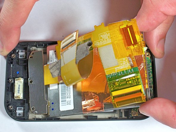
Remove one 4.0-mm #00 Phillips screws from the silver bracket holding the screen assembly in place.
-
-
Este passo não foi traduzido. Ajude a traduzi-lo
-
Remove the screen by using the spudger to gently but firmly pry the screen away from the outer case.
-
Use your hand to lift the screen completely away from the case.
-


Cancelar: não concluí este guia.
Uma outra pessoa concluiu este guia.
Equipe

University of Kentucky Louisville, Team 1-4, Chamberlain Spring 2013 Membro de University of Kentucky Louisville, Team 1-4, Chamberlain Spring 2013
LOUISVILLE-CHAMBERLAIN-S13S1G4
Membros da 3
Autoria de 8 guias