Esta versão pode conter edições incorretas. Mude para o último instantâneo verificado.
O que você precisa
-
Este passo não foi traduzido. Ajude a traduzi-lo
-
Using the standard metal spudger, begin by prying at the bottom of the plain rubber end cap (the end without the USB or auxiliary input).
-
-
Este passo não foi traduzido. Ajude a traduzi-lo
-
Continue prying around the end panel, prying at different points until the entire panel is out of its seating.
-
Carefully remove the end panel.
-
-
Este passo não foi traduzido. Ajude a traduzi-lo
-
Slide out the rubber foot located on the bottom of the case.
-
-
Este passo não foi traduzido. Ajude a traduzi-lo
-
Using a T6 bit, remove the flat topped 5mm screw located on the bottom of the casing, underneath the rubber foot.
-
-
Este passo não foi traduzido. Ajude a traduzi-lo
-
Push against the side without end cap to slide the internal components out of the case.
-
While holding the metal outset casing with one hand, press on the black inner plastic casing with your thumb.
-
-
Este passo não foi traduzido. Ajude a traduzi-lo
-
Using the standard metal spudger, carefully pry up the top 2 plastic tabs which hold the exterior button and port cover onto the interior plastic frame.
-
-
-
Este passo não foi traduzido. Ajude a traduzi-lo
-
Using the classic metal spudger, pry up the bottom 2 tabs attaching the other side of the button panel.
-
-
Este passo não foi traduzido. Ajude a traduzi-lo
-
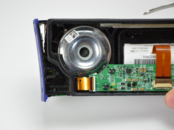
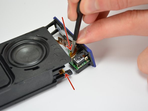
Carefully lift out the end panel.
-
Unplug both the connection ribbon and the ZIF ribbon using tweezers or your hands.
-
-
Este passo não foi traduzido. Ajude a traduzi-lo
-
Remove the 5mm T6 screw holding the port assembly onto the end cap.
-
-
Este passo não foi traduzido. Ajude a traduzi-lo
-
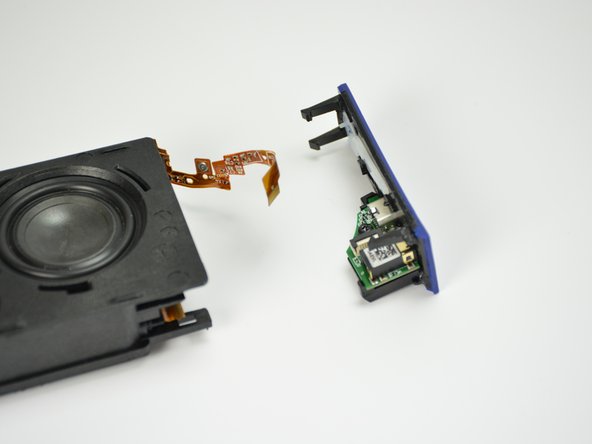
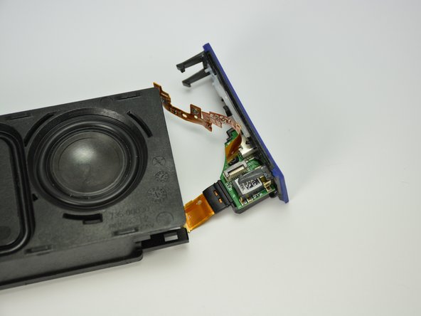
Disconnect the Motherboard connection ribbon from the motherboard.
-
-
Este passo não foi traduzido. Ajude a traduzi-lo
-
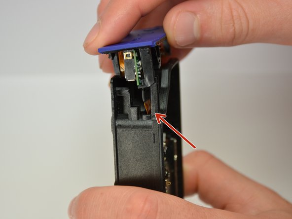
Very carefully pull the motherboard connection ribbon through the plastic casing, removing it from the plastic casing.
-
-
Este passo não foi traduzido. Ajude a traduzi-lo
-
Insert the connection ribbon into its ZIF connection port on the bottom of the new port assembly
-
-
Este passo não foi traduzido. Ajude a traduzi-lo
-
Position the new port assembly on the end cap and reinsert the 5mm T6 screw.
-
-
Este passo não foi traduzido. Ajude a traduzi-lo
-
Reconnect the button ribbon connector on the top of the port assembly.
-
-
Este passo não foi traduzido. Ajude a traduzi-lo
-
Reconnect the endcap to the plastic housing.
-
While you reconnect the endcap to the plastic housing, carefully position the ribbon slide through the ribbon slit and into the plastic casing.
-
-
Este passo não foi traduzido. Ajude a traduzi-lo
-
Snap the end cap back onto the inner plastic casing and reconnect the ZIF ribbon to the motherboard.
-


Cancelar: não concluí este guia.
5 outras pessoas executaram este guia.

Equipe

Cal Poly, Team 12-1, Lancaster Spring 2015 Membro de Cal Poly, Team 12-1, Lancaster Spring 2015
CPSU-LANCASTER-S15S12G1
Membros da 5
Autoria de 11 guias