Esta versão pode conter edições incorretas. Mude para o último instantâneo verificado.
O que você precisa
-
Este passo não foi traduzido. Ajude a traduzi-lo
-
Make sure battery-lock is in the unlock position.
-
Slide button to the left.
-
-
Este passo não foi traduzido. Ajude a traduzi-lo
-
Remove the two 5.62 mm screws from the optical drive cover.
-
-
Este passo não foi traduzido. Ajude a traduzi-lo
-
Remove the optical drive cover.
-
A plastic opening tool or a fingernail may be helpful in lifting it from its groove.
-
-
Este passo não foi traduzido. Ajude a traduzi-lo
-
Using the inset divot, push the optical drive out of the laptop to remove.
-
-
Este passo não foi traduzido. Ajude a traduzi-lo
-
Push the bottom left corner of the CD Drive until the drive protrudes from the case.
-
When a good amount of the CD Drive is showing on the right side, gently pull it out completely.
-
-
Este passo não foi traduzido. Ajude a traduzi-lo
-
Lift up the cover panel using a plastic opening tool.
-
-
Este passo não foi traduzido. Ajude a traduzi-lo
-
Remove the 5.64 mm screw from the bottom of the crossing bar.
-
Remove the crossing bar.
-
-
Este passo não foi traduzido. Ajude a traduzi-lo
-
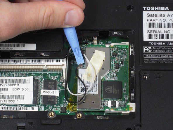
Use a plastic opening tool to disconnect the black and white antenna cable's connectors from the Wi-Fi card.
-
-
-
Este passo não foi traduzido. Ajude a traduzi-lo
-
Use fingers to push the clips away from memory card.
-
-
Este passo não foi traduzido. Ajude a traduzi-lo
-
Use the plastic opening tool to lift up the top panel all the way along the keyboard until it loosens.
-
-
Este passo não foi traduzido. Ajude a traduzi-lo
-
Remove the top panel by popping the panel out the top left socket, then do the same with the right side.
-
-
Este passo não foi traduzido. Ajude a traduzi-lo
-
Remove the two 3.67 mm screws from the top corners of the keyboard.
-
-
Este passo não foi traduzido. Ajude a traduzi-lo
-
Remove the cable connecting the keyboard with the motherboard.
-
Lift up and remove the keyboard.
-
-
Este passo não foi traduzido. Ajude a traduzi-lo
-
Gently pull the black and white wires out of the upper case.
-
-
Este passo não foi traduzido. Ajude a traduzi-lo
-
Remove the 8.6 mm screw on left side of upper case.
-
-
Este passo não foi traduzido. Ajude a traduzi-lo
-
Remove two 8.6 mm screws on the back corners of the laptop.
-
-
Este passo não foi traduzido. Ajude a traduzi-lo
-
Use the Phillips screwdriver to remove the two 3.7 mm screws from the battery compartment.
-
Then remove the fourteen 8.6 mm screws from the bottom of the case.
-
-
Este passo não foi traduzido. Ajude a traduzi-lo
-
Use the screwdriver to remove six 8.6 mm screws from the top of the case.
-
-
Este passo não foi traduzido. Ajude a traduzi-lo
-
Use the plastic opening tool to remove the two speaker wire connectors and the trackpad connector from the motherboard.
-
-
Este passo não foi traduzido. Ajude a traduzi-lo
-
With the plastic opening tool, pry around the entire laptop to separate the upper case.
-
-
Este passo não foi traduzido. Ajude a traduzi-lo
-
Using the Phillips Screwdriver, remove the two 8.6 mm screws from the front edge of the motherboard.
-
-
Este passo não foi traduzido. Ajude a traduzi-lo
-
Remove the four screws holding the ports to the rear panel using the 3/16" Wrench.
-
-
Este passo não foi traduzido. Ajude a traduzi-lo
-
Lift up on the front edge of the motherboard while gently prying the case away from the ports on the right side of the computer.
-
Repeat with the left side.
-
-
Este passo não foi traduzido. Ajude a traduzi-lo
-
Lift the motherboard's front edge up and then slide it forward.
-


Cancelar: não concluí este guia.
3 outras pessoas executaram este guia.
Equipe

Cal Poly, Team 4-43, Amido Fall 2010 Membro de Cal Poly, Team 4-43, Amido Fall 2010
CPSU-AMIDO-F10S4G43
Membros da 5
Autoria de 39 guias