Esta versão pode conter edições incorretas. Mude para o último instantâneo verificado.
O que você precisa
-
Este passo não foi traduzido. Ajude a traduzi-lo
-
Remove the four Torx T5 screws from the back panel.
-
-
Este passo não foi traduzido. Ajude a traduzi-lo
-
Wedge a spudger in between the front and back panel.
-
Apply leverage downwards to the spudger in order to remove the back panel.
-
-
Este passo não foi traduzido. Ajude a traduzi-lo
-
Slide the battery out from under the brown wire-tape.
-
Be careful of the wires still connected to the other end of the battery. Do not pull or damage may occur.
-
-
Este passo não foi traduzido. Ajude a traduzi-lo
-
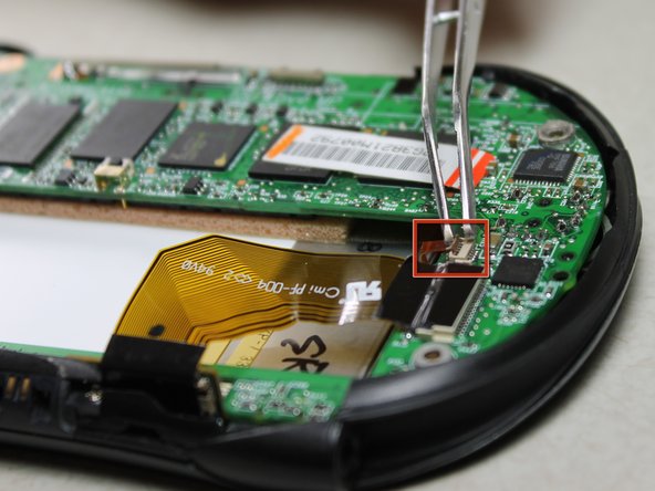
Slowly pull the white plug from its receptor. Grasp its sides firmly with a pair of tweezers and gently wiggle from side to side.
-
-
-
Este passo não foi traduzido. Ajude a traduzi-lo
-
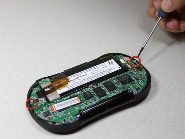
Unscrew the 2 Philips #00 screws on each end of the motherboard.
-
-
Este passo não foi traduzido. Ajude a traduzi-lo
-
Unscrew the 2 Philips #00 screws on each side of the charging port.
-
-
Este passo não foi traduzido. Ajude a traduzi-lo
-
Disconnect 2 brown wire-tape ends from each end of the motherboard. Gently pull straight out with tweezers.
-
-
Este passo não foi traduzido. Ajude a traduzi-lo
-
Grasp the upper left edge of the motherboard and slide diagonally up and left away from the auxiliary port entrance.
-
-
Este passo não foi traduzido. Ajude a traduzi-lo
-
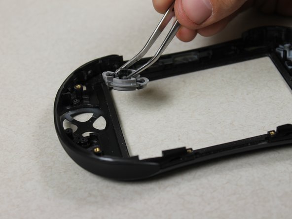
Unscrew the 2 silver Philips #00 screws from both sides of the directional pad component on the front casing.
-
-
Este passo não foi traduzido. Ajude a traduzi-lo
-
Take out the 2 pieces of the directional pad with tweezers.
-


Cancelar: não concluí este guia.
Uma outra pessoa concluiu este guia.
Equipe

Cal Poly, Team 10-33, Amido Winter 2012 Membro de Cal Poly, Team 10-33, Amido Winter 2012
CPSU-AMIDO-W12S10G33
Membros da 4
Autoria de 10 guias