Esta versão pode conter edições incorretas. Mude para o último instantâneo verificado.
O que você precisa
-
Este passo não foi traduzido. Ajude a traduzi-lo
-
Remove the five 4.0 mm Phillips #000 screws on the back panel.
-
-
Este passo não foi traduzido. Ajude a traduzi-lo
-
Using the Spudger, remove the back panel from the device.
-
The loose piece circled in the picture will most likely fall off the camera housing.
-
-
Este passo não foi traduzido. Ajude a traduzi-lo
-
Remove the two 2.15mm Phillips #000 screws from the circuit board.
-
Gently pull on the ribbon wire from ZIF connector with the tweezers to remove the button board.
-
-
Este passo não foi traduzido. Ajude a traduzi-lo
-
Remove the four 3.75 mm Phillips #000 screws from the LCD back panel.
-
-
Este passo não foi traduzido. Ajude a traduzi-lo
-
Lift the back panel and separate the LCD Screen by prying it up.
-
Remove the back panel.
-
-
Este passo não foi traduzido. Ajude a traduzi-lo
-
Gently pull on the ribbon wire disconnecting from the ZIF connector (connecting the LCD screen to the motherboard) with the tweezers.
-
-
-
Este passo não foi traduzido. Ajude a traduzi-lo
-
With plastic opening tool, gently pry loose the front panel.
-
Separate front panel from the camera housing.
-
-
Este passo não foi traduzido. Ajude a traduzi-lo
-
Remove the lens housing by pushing it, from the front, through the housing and lifting it out.
-
Gently pull on the large ribbon wire (connecting the Lens housing to the motherboard via ZIF connector) with the tweezers.
-
Gently pull on the small ribbon wire (connecting the Lens housing to the motherboard) with the tweezers.
-
-
Este passo não foi traduzido. Ajude a traduzi-lo
-
Remove the single 3.75 mm Phillips #000 screw from the base of the motherboard.
-
-
Este passo não foi traduzido. Ajude a traduzi-lo
-
Remove the two 3.5 mm Phillips #000 screws from the secondary board that is attached to the flash bulb.
-
-
Este passo não foi traduzido. Ajude a traduzi-lo
-
Use the tweezers. Move the thick red cable, attached to the secondary board, outside of its place in the camera housing.
-
Gently pull on the red/black wire in order to free the photo lens cylinder from the housing.
-
Remove the secondary board from its position and move it upward, out of the way.
-
-
Este passo não foi traduzido. Ajude a traduzi-lo
-
Using the tweezers, pull the indicator bulb out , freeing it from its position on the housing.
-
Thread the indicator bulb under and through the secondary boards position.
-
-
Este passo não foi traduzido. Ajude a traduzi-lo
-
Using the tweezers, remove the black/red speaker wire from camera housing.
-
Pry loose and remove the speaker from the camera housing.
-
-
Este passo não foi traduzido. Ajude a traduzi-lo
-
Using the spudger, remove the mini speaker from the housing.
-
-
Este passo não foi traduzido. Ajude a traduzi-lo
-
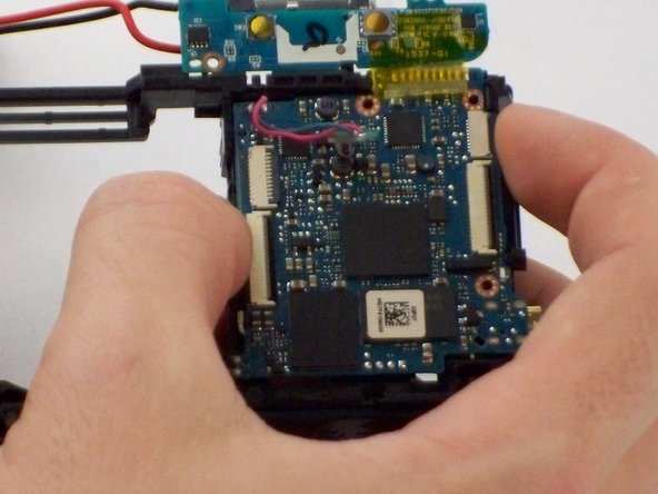
Pull up on the bottom-half of the motherboard, slightly removing it from its position in the housing.
-
With enough force, pull up on the top right of the motherboard, pulling it entirely from its position in the housing.
-
-
Este passo não foi traduzido. Ajude a traduzi-lo
-
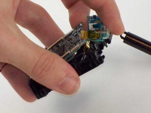
Once apart, completely separate motherboard from the housing.
-


Cancelar: não concluí este guia.
2 outras pessoas executaram este guia.
Equipe

USF Tampa, Team 17-5, Blackwell Winter 2016 Membro de USF Tampa, Team 17-5, Blackwell Winter 2016
USFT-BLACKWELL-W16S17G5
Membros da 5
Autoria de 5 guias