Introdução
RC sockets are the red and white jacks in the back of the BDP-S1 that take in audio inputs. If one of them gets faulty, the circuit board needs to be removed in order for them to be replaced.
O que você precisa
-
-
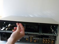
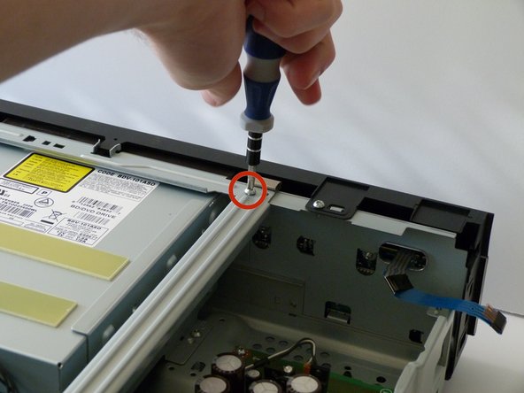
Remove the 12mm screws with the Philips #2 screwdriver which keep the plastic panels in place.
-
Don't forget, there are two more 12mm screws on the other side as well.
-
-
-
-
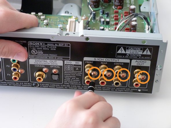
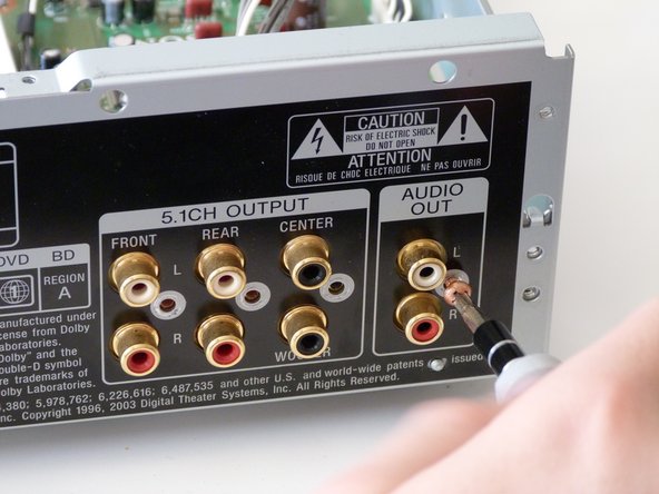
These are the RC sockets. They are the audio output that sends a signal set of speakers.
-
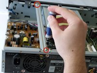
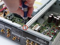
Unscrew the frame to access the circuit board.
-
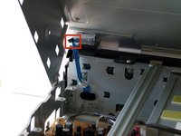
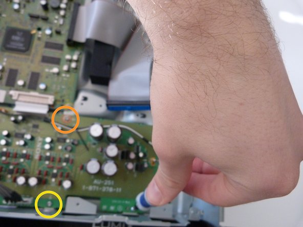
Remove the four screws circled in the figure using a Phillips #2 Screwdriver.
-
-
-
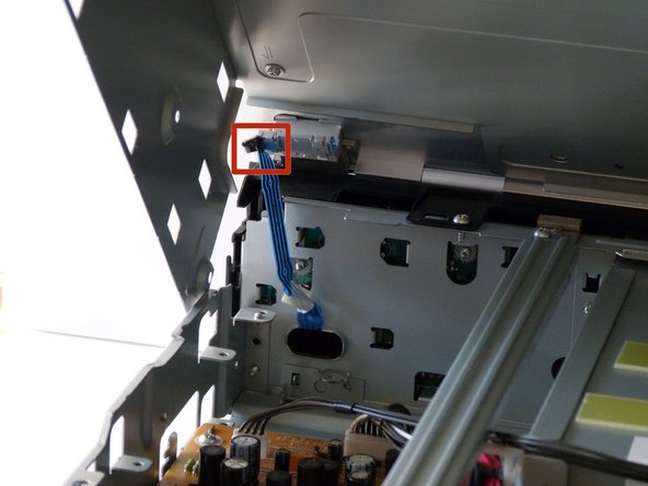
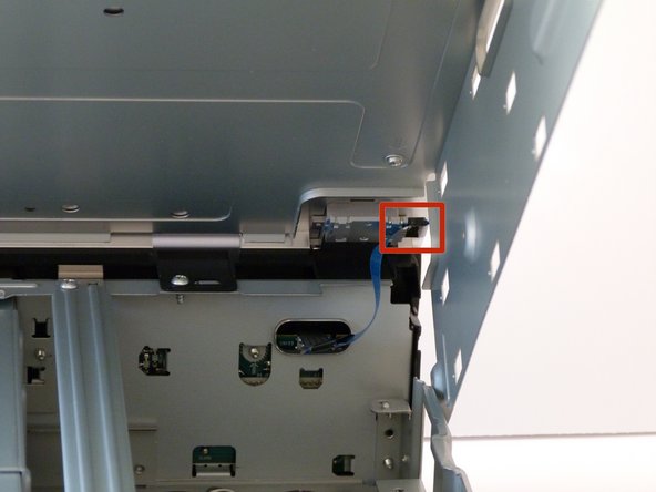
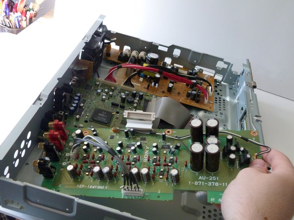
Remove the cable ribbon that is attached to the motherboard.
-
And voila! You have successfully taken out the circuit board.
-
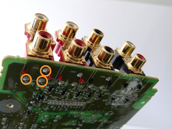
And here we see the solder that keeps the RC components strapped into the board. In order to get them off and put them back on, you'll need a soldering iron, wick, and solder itself.
-
If you don't know how to solder properly, there are plenty of helpful guides online, such as this one. Make sure to remove the solder all the way before removing the RC jacks, otherwise you could hurt the board.
-
Now you just have to take off the RC components, place the news ones in, and solder them into the board (again using a soldering guide if you need to).
-
Good work! Now celebrate by listening to your favorite movie!
-


When reassembling your device, solder in any RC components needed and then follow these instructions in reverse order.