Esta versão pode conter edições incorretas. Mude para o último instantâneo verificado.
O que você precisa
-
Este passo não foi traduzido. Ajude a traduzi-lo
-
Flip the vacuum on its underside, and use a coin to rotate the cam-screws on the bottom panel so that their grooves are parallel with the front of the vacuum.
-
-
Este passo não foi traduzido. Ajude a traduzi-lo
-
Squeeze the sides of the roller brush cover release clasp, and swing the cover open.
-
-
Este passo não foi traduzido. Ajude a traduzi-lo
-
Using a T20 screwdriver remove five 15.9 mm screws on the outside of the cover.
-
-
Este passo não foi traduzido. Ajude a traduzi-lo
-
Using a T20 screwdriver, remove three 13.4 mm screws from where the roller brush cover attaches to the bottom of the vacuum.
-
-
Este passo não foi traduzido. Ajude a traduzi-lo
-
Using a T20 screwdriver, remove two 13.4 mm screws from under the wheels.
-
-
-
Este passo não foi traduzido. Ajude a traduzi-lo
-
Using a T20 screwdriver, remove two 15.9 mm screws behind the vacuum wheels.
-
-
Este passo não foi traduzido. Ajude a traduzi-lo
-
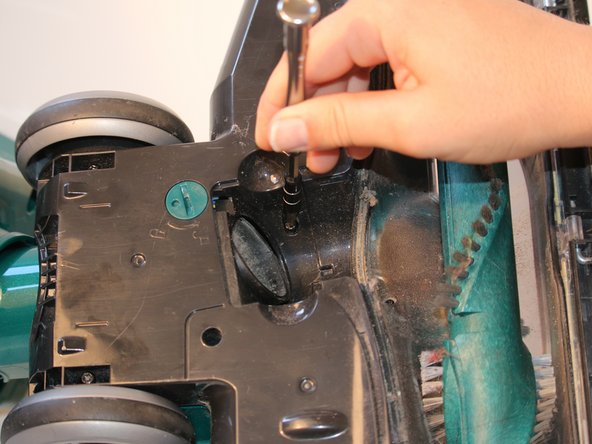
Using a PH0 screwdriver bit, remove the single 13.4 mm screw in between the roller brush and where the release clasp was attached.
-
-
Este passo não foi traduzido. Ajude a traduzi-lo
-
Using a T20 screwdriver, remove the single 13.4 mm screw from behind the belted end of the roller brush.
-
-
Este passo não foi traduzido. Ajude a traduzi-lo
-
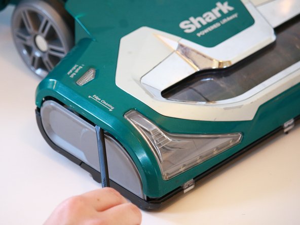
Flip the vacuum into the upright position, and use a spudger to open the front assembly cover by prying the seam where the colored front assembly and the grey side covers meet.
-
-
Este passo não foi traduzido. Ajude a traduzi-lo
-
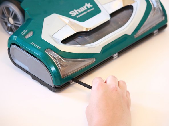
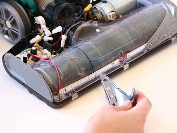
Use a spudger to remove the headlight covers by prying the seams where the headlight covers meet the bottom front of the vacuum.
-
-
Este passo não foi traduzido. Ajude a traduzi-lo
-
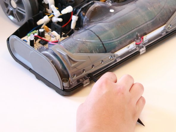
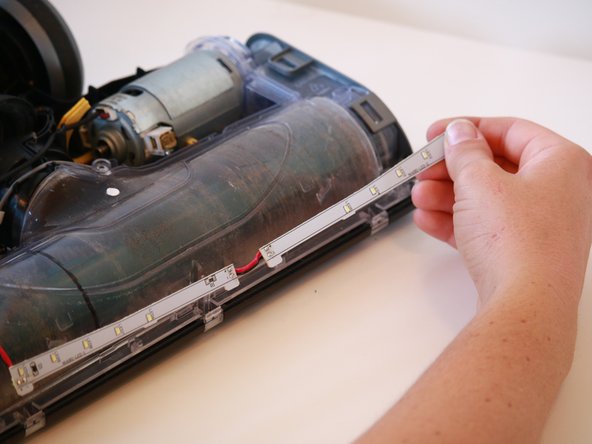
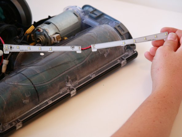
Pull the LED headlight strand up and away from where it is attached to the bottom front of the vacuum.
-
-
Este passo não foi traduzido. Ajude a traduzi-lo
-
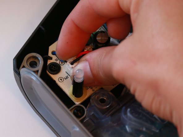
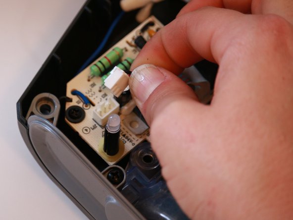
Pinch the tabs on the circuit board clasp for the LED headlight inwards , and pull the clasp up and away to detach the headlight.
-


Cancelar: não concluí este guia.
2 outras pessoas executaram este guia.
Equipe

Cal Poly, Team S4-G6, White Fall 2018 Membro de Cal Poly, Team S4-G6, White Fall 2018
CPSU-WHITE-F18S4G6
Membros da 4
Autoria de 12 guias