Esta versão pode conter edições incorretas. Mude para o último instantâneo verificado.
O que você precisa
-
Este passo não foi traduzido. Ajude a traduzi-lo
-
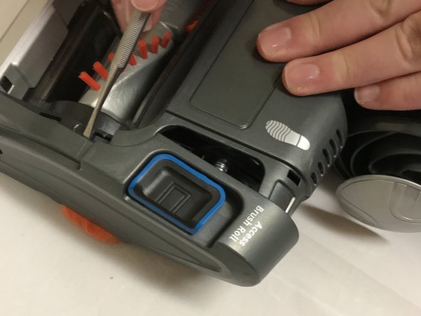
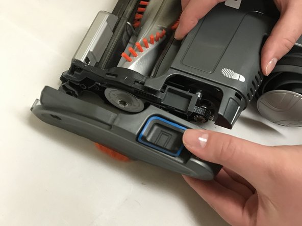
Press and slide the “access brush roll” buttons towards the text and lift plastic brush roll cover off.
-
-
Este passo não foi traduzido. Ajude a traduzi-lo
-
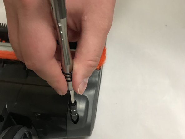
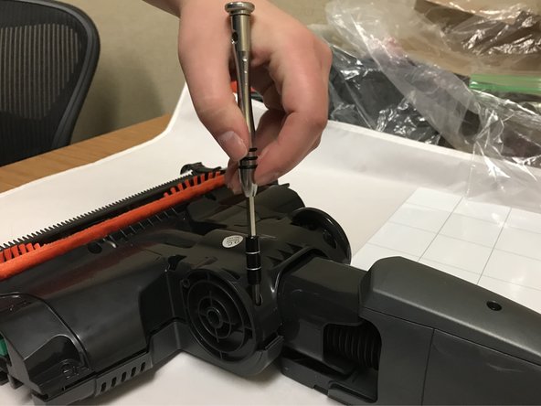
Gently pry the circular screw cover off of the side of the casing with the shoe print mark on it with the small metal spudger.
-
-
Este passo não foi traduzido. Ajude a traduzi-lo
-
Use a T20 screwdriver to unscrew the 12.3 mm screw beneath the cover you just removed.
-
-
Este passo não foi traduzido. Ajude a traduzi-lo
-
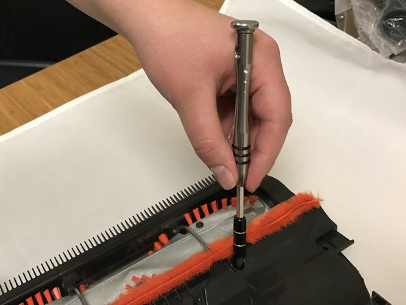
Move to the side of the casing with the shoe print mark. Use the T20 screwdriver to unscrew the 18mm screw.
-
-
Este passo não foi traduzido. Ajude a traduzi-lo
-
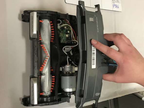
Use the small metal spudger to gently separate the side casing from the main body.
-
-
Este passo não foi traduzido. Ajude a traduzi-lo
-
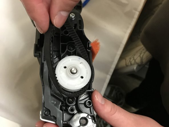
Use the large plastic opening tool to pry the rubber brushroll band towards you until the rubber brush roll band comes off of the small metal gear.
-
-
-
Este passo não foi traduzido. Ajude a traduzi-lo
-
Pull the rubber brush roll band out of the large white gear.
-
-
Este passo não foi traduzido. Ajude a traduzi-lo
-
Unscrew the six 18.7mm screws in the bottom casing using a T20 screwdriver.
-
-
Este passo não foi traduzido. Ajude a traduzi-lo
-
Remove the large black plastic plug using your fingers and/or long nose pliers.
-
-
Este passo não foi traduzido. Ajude a traduzi-lo
-
Remove large white plastic plug using your fingers and/or long nose pliers.
-
-
Este passo não foi traduzido. Ajude a traduzi-lo
-
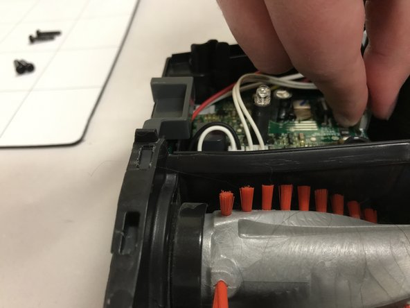
Squeeze tabs and remove small white plug with two white wires coming out of it.
-
-
Este passo não foi traduzido. Ajude a traduzi-lo
-
Squeeze tabs and remove small white plug with white and black wires coming out of it.
-
-
Este passo não foi traduzido. Ajude a traduzi-lo
-
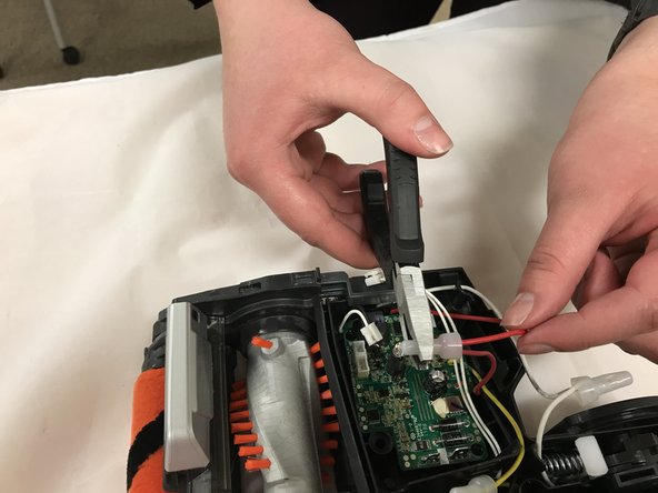
Squeeze the three plastic caps enclosing the crimped connection of the red, black and yellow wires extending outward from the motherboard to release the wires from the grip of the plastic caps.
-
-
Este passo não foi traduzido. Ajude a traduzi-lo
-
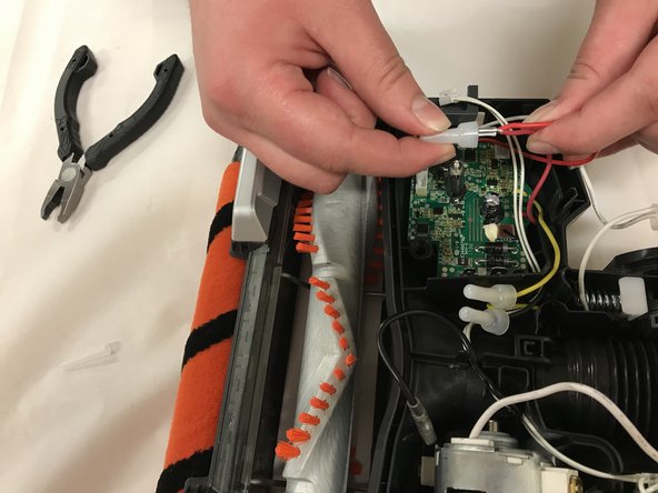
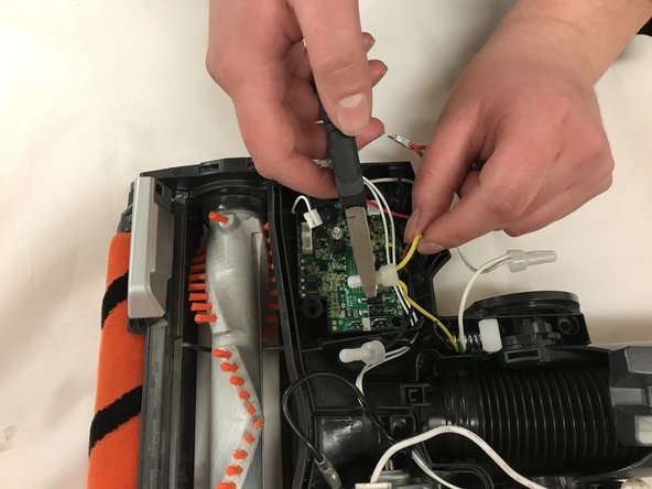
Remove the caps from the red, black and yellow wires to expose the three metal clamps.
-
-
Este passo não foi traduzido. Ajude a traduzi-lo
-
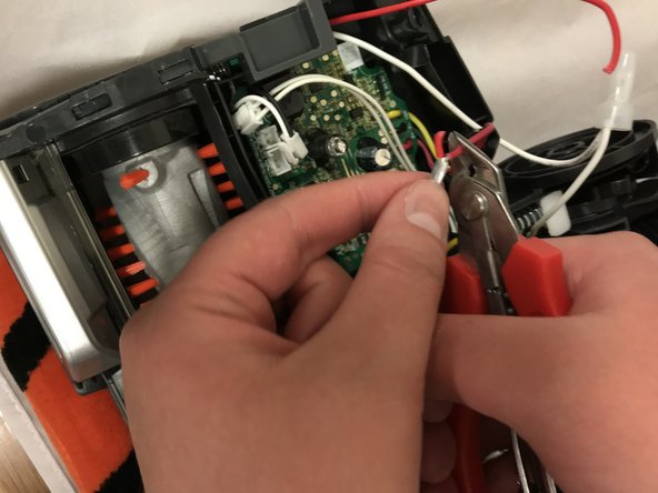
Cut the red wires extending beneath the metal clamp, right below the metal clamp holding the two wires together. Repeat process for black and yellow wires.
-
-
Este passo não foi traduzido. Ajude a traduzi-lo
-
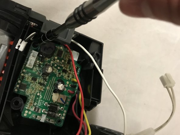
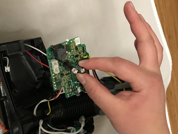
Unscrew the two 11.8mm screws in the motherboard using a T10 screwdriver.
-


Cancelar: não concluí este guia.
3 outras pessoas executaram este guia.

Equipe

Eastern Washington University, Team S4-G1, Crane Fall 2018 Membro de Eastern Washington University, Team S4-G1, Crane Fall 2018
EWU-CRANE-F18S4G1
Membros da 2
Autoria de 15 guias
2 comentários
Thanks for the guide. I had an issue where the lights would switch on but the roller would not spin. After taking it apart I found the issue. When putting the cover on the plastic tab that needs to engage the roller switch slides behind the ‘button’ for the switch.
hard to explain but if you take off the side where the motherboard is you will see the green micro switch follow the spring loaded button to the front of the unit. The plastic tab on the cover slides in besides it causing it not to engage the switch
This guide is for removal of the brush roller motherboard, yet is labelled as the IONFlex 2X motherboard which happens to be a number of PCBs in the hand held part of this unit.
Mis-leading title.