Introdução
Instructions on how to remove the photo array device from the Sanyo VPC-T850
O que você precisa
-
-
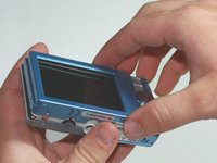
Make sure the camera is powered off by pressing and holding the small, square button embedded in the top rim of the camera.
-
-
-
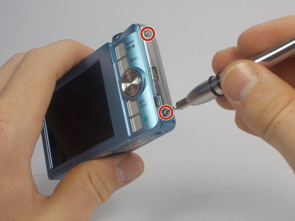
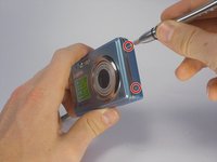
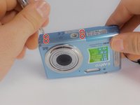
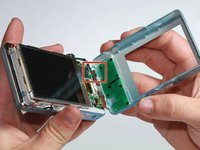
Using your Phillips #000 Screwdriver, remove the eight screws located around the sides and bottom of the camera.
-
-
-
-
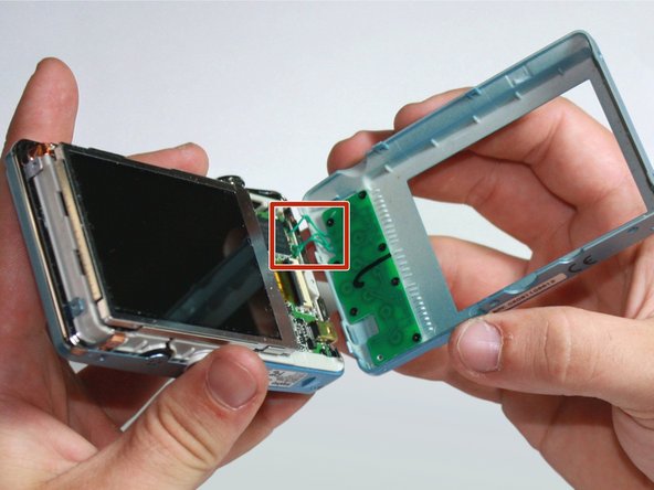
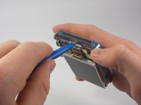
Flip the device over to where the display is located.
-
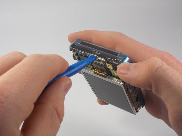
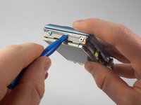
Using your plastic opening tool, lift the display out of its metal housing.
-


Conclusão
To reassemble your device, follow these instructions in reverse order.
Equipe

Cal Poly, Team 27-95, Amido Spring 2010 Membro de Cal Poly, Team 27-95, Amido Spring 2010
CPSU-AMIDO-S10S27G95
4 Membros
Autoria de 4 guias