Esta versão pode conter edições incorretas. Mude para o último instantâneo verificado.
O que você precisa
-
Este passo não foi traduzido. Ajude a traduzi-lo
-
Power the device down completely
-
Remove the SD card from the SD card slot.
-
-
Este passo não foi traduzido. Ajude a traduzi-lo
-
Use the prying tool to separate the front and rear panels by slipping the tool underneath the screen edge and sliding it around the entire device.
-
-
Este passo não foi traduzido. Ajude a traduzi-lo
-
Remove the battery Flex Cable from its socket by placing the pry tool under the wires and gently prying it out.
-
-
Este passo não foi traduzido. Ajude a traduzi-lo
-
Using the Phillips precision screw driver remove the six 4 mm screws holding the battery in place.
-
Once the battery is loose, remove as shown.
-
-
Este passo não foi traduzido. Ajude a traduzi-lo
-
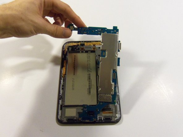
Using the Phillips #00 precisions screwdriver, remove the 12 4mm screws holding in the motherboard.
-
-
Este passo não foi traduzido. Ajude a traduzi-lo
-
Release all flex cable connections at the bottom section of the motherboard.
-
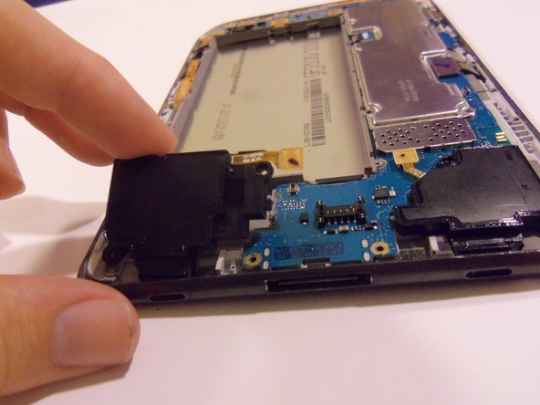
Using the plastic pry tool release connections for both loudspeakers.
-
Once disconnected gently remove the loudspeakers from the device.
-
-
-
Este passo não foi traduzido. Ajude a traduzi-lo
-
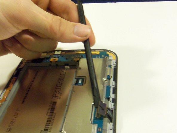
Release all flex cables on the right side of the device motherboard as shown.
-
Using the plastic pry tool, release the touch screen flex cable from its socket.
-
With the same tool release the LCD screen flex cable form its socket.
-
-
Este passo não foi traduzido. Ajude a traduzi-lo
-
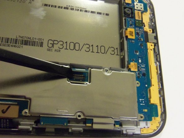
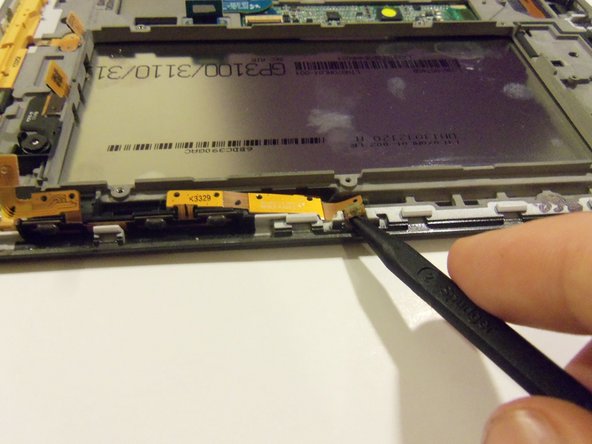
Release all flex cables on the upper portion of the motherboard.
-
Using the plastic pry tool release the sensor flex cable from its socket.
-
With the same tool release the camera flex cable from its socket.
-
Release the front camera flex cable from its socket.
-
Release the side button's flex cable from its socket.
-
-
Este passo não foi traduzido. Ajude a traduzi-lo
-
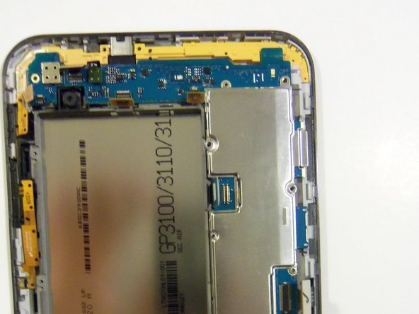
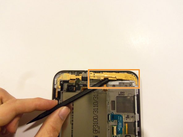
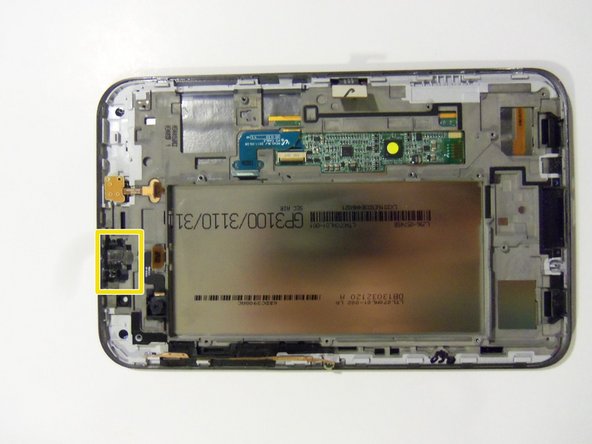
There is one more Flex cable to remove, it's to the right of the front camera connector (see previous picture with connector highlighted in yellow box). It connects the top microphone and headphone jack.
-
-
Este passo não foi traduzido. Ajude a traduzi-lo
-
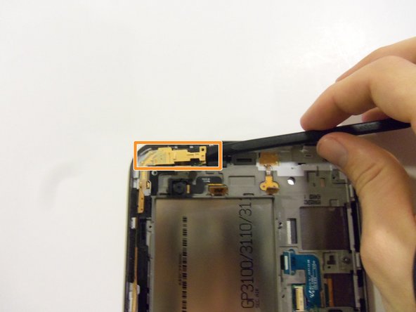
Release the button flex cable using the plastic spudger tool.
-
-
Este passo não foi traduzido. Ajude a traduzi-lo
-
Remove the main camera using the plastic spudger tool.
-
Using the plastic spudger tool, remove the two main spacers.
-
-
Este passo não foi traduzido. Ajude a traduzi-lo
-
Remove the front facing camera using the precision tweezers.
-
-
Este passo não foi traduzido. Ajude a traduzi-lo
-
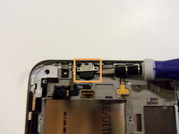
Remove the sensor flex cable using the flat-head screwdriver.
-
Remove the cover that is over the headphone jack using the precision flat-head screwdriver.
-
Remove the headphone jack using the precision flat-head screwdriver.
-
-
Este passo não foi traduzido. Ajude a traduzi-lo
-
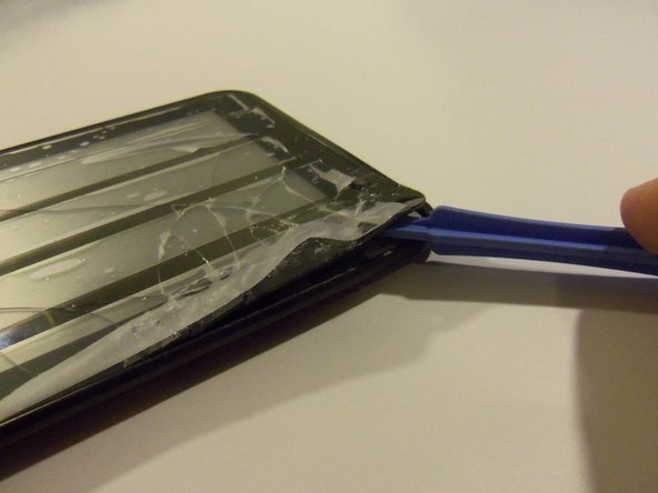
Place tape over the front of the touch screen to catch broken glass. The wider the tape the better.
-
Heat up the touch screen in some way to release the strong adhesive.
-
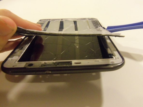
Using the safe pry tool, pry up the edge of the touch screen and slowly work your way around the entire device.
-
-
Este passo não foi traduzido. Ajude a traduzi-lo
-
Congratulations, this is what your device should look like after the touch screen has been removed.
-


Cancelar: não concluí este guia.
4 outras pessoas executaram este guia.
Equipe

Sam Houston State, Team 11-5, Blackburne Winter 2015 Membro de Sam Houston State, Team 11-5, Blackburne Winter 2015
SHSU-BLACKBURNE-W15S11G5
Membros da 3
Autoria de 4 guias