Esta versão pode conter edições incorretas. Mude para o último instantâneo verificado.
O que você precisa
-
Este passo não foi traduzido. Ajude a traduzi-lo
-
Pry with a plastic opening tool, or your fingernail, in the divot to the left of the rear-facing camera, near the power button.
-
-
Este passo não foi traduzido. Ajude a traduzi-lo
-
Lift the rear case by the corner nearest the divot and remove it from the phone.
-
-
Este passo não foi traduzido. Ajude a traduzi-lo
-
Use the flat end of a spudger, or your fingernail, to press the microSD card slightly deeper into its slot until you hear a click.
-
After the click, release the card and it will pop out of its slot.
-
Remove the microSD card.
-
-
Este passo não foi traduzido. Ajude a traduzi-lo
-
Insert a plastic opening tool, or your finger, into the notch of the battery compartment and lift the battery upward.
-
Remove the battery from your phone.
-
-
Este passo não foi traduzido. Ajude a traduzi-lo
-
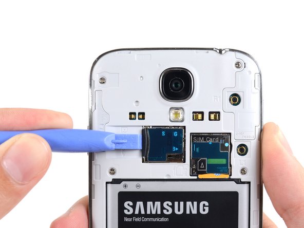
Use a plastic opening tool, or your fingernail, to press the SIM card slightly deeper into its slot until you hear a click.
-
After the click, release the card and it will pop out of its slot.
-
Remove the SIM card.
-
-
Este passo não foi traduzido. Ajude a traduzi-lo
-
Remove the nine 4.0 mm Phillips #00 screws securing the midframe to the display assembly.
-
-
-
Este passo não foi traduzido. Ajude a traduzi-lo
-
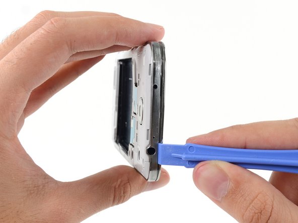
Starting on the volume button side of the phone, insert your plastic opening tool between the chrome bezel around the display glass and the larger chrome border piece. Look for the seam between the two.
-
Slide the opening tool along the seam, separating the plastic clips as you go.
-
-
Este passo não foi traduzido. Ajude a traduzi-lo
-
Continue prying around the corner of the phone.
-
Slide your opening tool along the seam between the midframe and display along the bottom of the device, releasing more of the plastic clips.
-
-
Este passo não foi traduzido. Ajude a traduzi-lo
-
Again, pry around the corner, to the power button side.
-
Slide the opening tool along the seam.
-
-
Este passo não foi traduzido. Ajude a traduzi-lo
-
Continue sliding the opening tool around the top of the phone, releasing the last of the clips and freeing the midframe from the display assembly.
-
-
Este passo não foi traduzido. Ajude a traduzi-lo
-
Use the flat end of a spudger to disconnect the USB board cable connector from the motherboard.
-
-
Este passo não foi traduzido. Ajude a traduzi-lo
-
Gently insert the point of a spudger between the USB port and the USB port bracket to pry one side of the bracket off of its post.
-
-
Este passo não foi traduzido. Ajude a traduzi-lo
-
Disconnect the soft button cable from the USB board cable.
-
Disconnect the antenna cable connector from the USB board.
-
-
Este passo não foi traduzido. Ajude a traduzi-lo
-
Gently insert the flat end of a spudger beneath the USB board to free it from the adhesive holding it in place.
-


Cancelar: não concluí este guia.
206 outras pessoas executaram este guia.


24 comentários
I found this guide excellent and it is very easy to do. I didnt have the plastic opening tool but I do have a long thumbnail. It worked very well.
Too bad the replacement board I got has a defective soft button connector. I had to disassemble the phone 3 times. I thought I did It wrong the 1st time. Opened the phone a 2nd time to check.... closed the phone... nada.... USB changer works but no soft keys... put my old board back in to check the soft buttons and they work. Sent an email to the company that I bought the board from... still no answer after 24hrs. If I still have no answer by the end of the week I will post which company sold me the defect board so no one else gets burned from them. I will then try to unsolder the USB from the new board to replace the USB on my old one.
This guide needs an update as it does not include the 4G antenna on the left side of the device that is under the USB cable and hooks up at the bottom left on the USB board up to just beside the USB connector above the battery. Pictures 12, 15, & 16 will need updated to show this cable.
To follow rnbhays' comment about the antenna connector on the left, it is specifically for i545 Verizon models.
I strongly suggest people to disconnect both left and right cables from the USB board prior to removing it. While doing so, my tool slipped and I accidentally broke the left cable. Thankfully I was able to crimp the connector back on the cable with tweezers and a magnifying glass 'til I get another cable ordered.
It also applies to the Sprint version as well. I have an LTE cable on the left side, and had to be very careful purchasing a replacement part to make sure it was the right one.
After replacement my microphone element isn't working. Possible reasons?