Esta versão pode conter edições incorretas. Mude para o último instantâneo verificado.
O que você precisa
-
Este passo não foi traduzido. Ajude a traduzi-lo
-
Insert a SIM card eject tool, bit, or a straightened paperclip into the hole on the SIM tray, located at the top edge of the phone next to the plastic antenna band.
-
Press firmly to eject the tray.
-
Remove the SIM card tray.
-
-
Este passo não foi traduzido. Ajude a traduzi-lo
-
Unplug and power off your phone before you begin.
-
Heat an iOpener and apply it to the back cover's right edge for two minutes.
-
As you wait, take a look at the image of the removed back cover and take note of where the adhesive is located.
-
-
Este passo não foi traduzido. Ajude a traduzi-lo
-
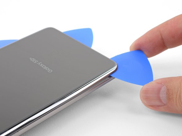
Apply a suction cup to the back of the phone, as close to the center of the right edge as possible (where the adhesive is narrowest).
-
Pull on the suction cup with strong, steady force to create a gap between the back cover and the frame.
-
Insert the point of an opening pick into the gap.
-
If you are having trouble creating a gap, your best bet is to apply more heat to the edge and try the previous step again.
-
You can try applying a few drops of high concentration (over 90%) isopropyl alcohol into the seam to help loosen the adhesive.
-
-
Este passo não foi traduzido. Ajude a traduzi-lo
-
Rest the heated right edge of the phone on something that is about 0.5 inches (13 mm) thick. This angles the phone for the opening tool.
-
Brace the left edge of the phone with your fingers so that the phone won't slide. Pull on the suction cup with firm pressure.
-
Press the edge of an opening tool into the seam between the back cover and the frame.
-
Slide the opening tool back and forth along the seam a few times.
-
-
Este passo não foi traduzido. Ajude a traduzi-lo
-
Slide the opening pick along the edge of the phone, slicing through the adhesive.
-
Leave a pick in the seam to prevent the adhesive from re-sealing.
-
-
Este passo não foi traduzido. Ajude a traduzi-lo
-
Apply a heated iOpener to the bottom edge of the phone for two minutes.
-
-
Este passo não foi traduzido. Ajude a traduzi-lo
-
Insert an opening pick into the right edge near the bottom right corner.
-
Carefully slide the pick around the corner. Continue cutting along the bottom edge and around the bottom left corner.
-
Leave an opening pick in the seam to prevent the adhesive from re-sealing.
-
-
Este passo não foi traduzido. Ajude a traduzi-lo
-
Continue heating and slicing around the remaining edges of the phone.
-
-
Este passo não foi traduzido. Ajude a traduzi-lo
-
Once you have sliced around the phone, twist an opening pick in one of the edges to help separate the back cover from the frame.
-
Lift the back cover slowly. Use opening picks to slice any remaining adhesive.
-
Remove the back cover.
-
-
-
Este passo não foi traduzido. Ajude a traduzi-lo
-
Remove the nine 4 mm Phillips screws securing the top midframe to the phone.
-
-
Este passo não foi traduzido. Ajude a traduzi-lo
-
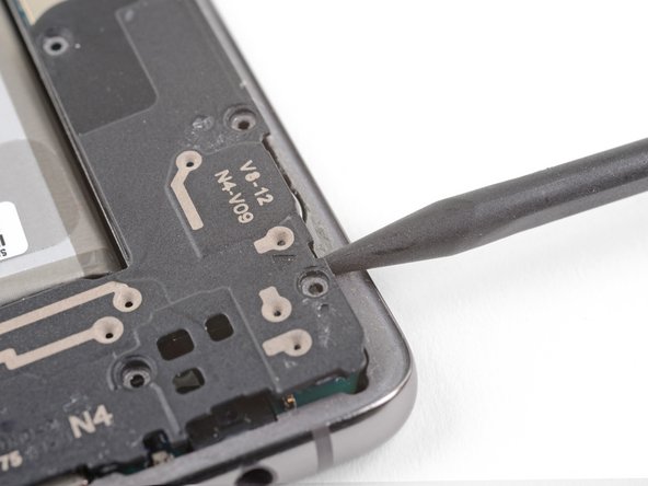
Insert the point of a spudger into the notch on the right edge of the midframe, near the Bixby button.
-
Pry up to loosen the midframe from the phone.
-
-
Este passo não foi traduzido. Ajude a traduzi-lo
-
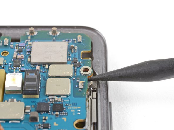
Insert the point of a spudger into the notch on the left edge of the phone, located near the power button.
-
Pry up to loosen the midframe from the phone.
-
-
Este passo não foi traduzido. Ajude a traduzi-lo
-
Lift the midframe from the top corners and remove it from the phone.
-
Align the midframe's top edge to the phone and lay the frame down on the phone.
-
Use fingers to apply pressure along the midframe perimeter to snap the midframe clips back into place. The edges should sit flush against the phone edge.
-
-
Este passo não foi traduzido. Ajude a traduzi-lo
-
Insert the flat end of a spudger underneath the battery connector, which is attached to the motherboard below the rear-facing camera.
-
Pry upwards to disconnect the connector from its socket.
-
Gently push the battery's flex cable away from the motherboard socket to prevent accidental contact.
-
-
Este passo não foi traduzido. Ajude a traduzi-lo
-
Remove the seven 4 mm Phillips screws securing the lower midframe to the phone.
-
-
Este passo não foi traduzido. Ajude a traduzi-lo
-
Insert the point of a spudger in the notch near the bottom right corner of the lower midframe. It is marked by a small triangle.
-
Pry up to release the midframe from the phone.
-
-
Este passo não foi traduzido. Ajude a traduzi-lo
-
Grasp the loosened end of the midframe with your fingers and lift upwards slowly.
-
Wiggle the midframe slightly to help release the remaining edge clips.
-
Remove the lower midframe. The loudspeaker is built into the lower midframe.
-
-
Este passo não foi traduzido. Ajude a traduzi-lo
-
Use the flat end of a spudger to pry up and disconnect the display connector from its motherboard socket, located near the bottom right corner of the phone.
-
-
Este passo não foi traduzido. Ajude a traduzi-lo
-
Use the flat end of a spudger to pry up and disconnect the headphone jack's connector from its motherboard socket.
-
-
Este passo não foi traduzido. Ajude a traduzi-lo
-
Remove the three Phillips screws securing the motherboard to the phone:
-
One 3.8 mm screw
-
Two 3.7 mm screws
-
-
Este passo não foi traduzido. Ajude a traduzi-lo
-
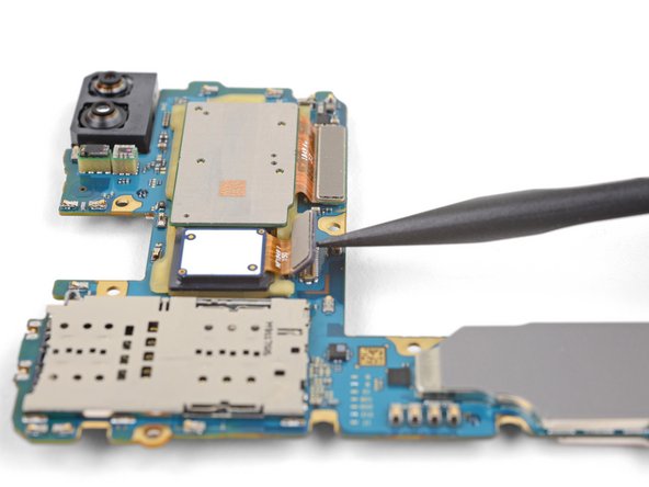
Insert the point of a spudger underneath the right edge of the motherboard, near the volume up button.
-
Pry up gently to loosen the motherboard from its recess.
-
-
Este passo não foi traduzido. Ajude a traduzi-lo
-
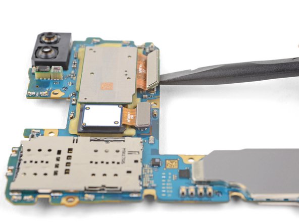
Using your fingers, grasp the motherboard by the top corners.
-
Lift the motherboard edge slightly out of its recess. Be careful not to snag any cables along the way.
-
Pull the motherboard towards the top edge of the phone while wiggling the board slightly. This will loosen the charging port from its socket.
-
Once the charging port is freed from its socket, remove the motherboard.
-
Gently push the motherboard against the bottom edge of the phone until the charging port is completely seated.
-
Lower the motherboard and press into place. Be careful not to trap any cables underneath the motherboard. The board should sit flush against the frame.
-
-
Este passo não foi traduzido. Ajude a traduzi-lo
-
Flip the motherboard over.
-
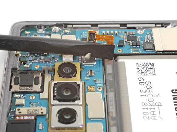
Use the flat end of a spudger to pry up and disconnect the two camera connectors from their sockets on the motherboard.
-
-
Este passo não foi traduzido. Ajude a traduzi-lo
-
Heat an iOpener and lay it over the rear-facing camera module for one minute. This helps loosen the adhesive holding the camera module to the motherboard.
-
-
Este passo não foi traduzido. Ajude a traduzi-lo
-
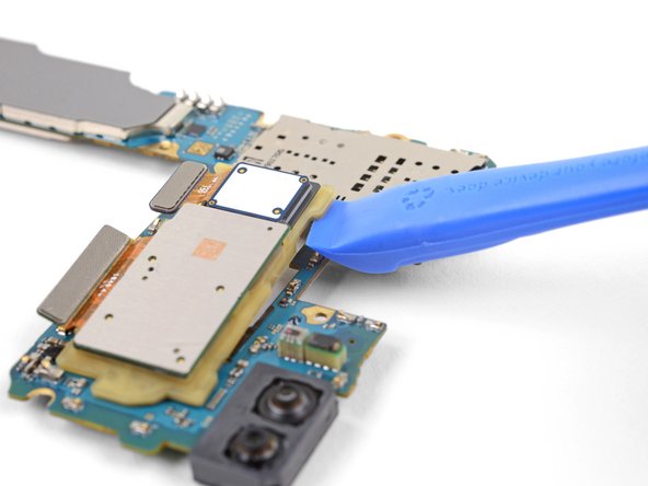
Insert the point of a spudger under the top-left corner of the camera module, where there is a small notch.
-
Pry up to loosen the camera module from the motherboard.
-
-
Este passo não foi traduzido. Ajude a traduzi-lo
-
Insert the edge of an opening tool under the loosened corner of the camera module.
-
Pry up to release the camera module from the motherboard.
-
Continue prying around the camera module with the opening tool until the module is freed from the motherboard.
-


Cancelar: não concluí este guia.
10 outras pessoas executaram este guia.

