Esta versão pode conter edições incorretas. Mude para o último instantâneo verificado.
O que você precisa
-
Este passo não foi traduzido. Ajude a traduzi-lo
-
Insert a SIM card eject tool straight into the hole in the SIM card tray.
-
Press to eject the SIM card tray.
-
-
Este passo não foi traduzido. Ajude a traduzi-lo
-
Power off your phone before beginning disassembly.
-
Use a hairdryer, a heatgun, or prepare an iOpener and apply it to the right edge of the back of the phone for about a minute to soften the adhesive underneath.
-
-
Este passo não foi traduzido. Ajude a traduzi-lo
-
Apply a suction handle to the back cover.
-
Lift with a suction handle to create a gap between the back cover and the frame of the phone.
-
Insert an opening pick into the gap.
-
-
Este passo não foi traduzido. Ajude a traduzi-lo
-
Note that there is more adhesive along the top edge and around the camera bezel than around the rest of the phone.
-
Cut carefully around the left edge near the fingerprint sensor or you risk damaging the ribbon cable inside.
-
-
Este passo não foi traduzido. Ajude a traduzi-lo
-
Starting from the center, cut the adhesive up and down the right side with an opening pick.
-
-
Este passo não foi traduzido. Ajude a traduzi-lo
-
Leave an opening pick in the upper-right corner.
-
Use another opening pick to cut the adhesive around the bottom-right corner.
-
Leave that opening pick in the phone.
-
-
Este passo não foi traduzido. Ajude a traduzi-lo
-
Use a heat gun or hair dryer or apply a heated iOpener to the left side of the rear panel for at three minutes to soften the adhesive underneath.
-
-
Este passo não foi traduzido. Ajude a traduzi-lo
-
Insert an opening pick into the lower-left corner of the rear panel.
-
Using another opening pick, cut the adhesive along the left edge of the rear panel.
-
-
Este passo não foi traduzido. Ajude a traduzi-lo
-
Using the inserted opening pick, carefully cut the adhesive around the upper-left corner of the rear panel.
-
Finally, cut the last of the adhesive along the top of the phone.
-
-
Este passo não foi traduzido. Ajude a traduzi-lo
-
Separate the right side of the rear cover first.
-
Tilt the cover up along the left edge to expose the fingerprint sensor ribbon cable.
-
-
-
Este passo não foi traduzido. Ajude a traduzi-lo
-
Use the tip of a spudger to pry the fingerprint sensor ribbon cable up and out of its socket.
-
-
Este passo não foi traduzido. Ajude a traduzi-lo
-
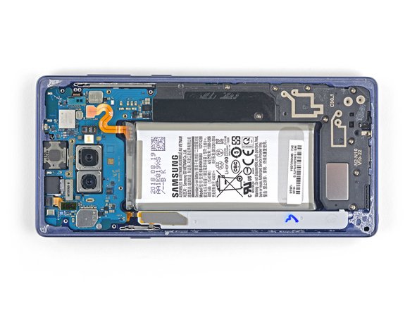
Remove the back cover.
-
Use tweezers to peel away any remaining adhesive from the phone's chassis. Then clean the adhesion areas with high concentration isopropyl alcohol (at least 90%) and a lint-free cloth to prep the surface for the new adhesive. You don't have to clear out adhesive down to the plastic but larger pieces should be removed.
-
Turn on your phone and test your repair before installing new adhesive and resealing the phone.
-
Carefully apply the new adhesive to the back cover, then line up one edge of the glass against the phone chassis and firmly press the glass into the phone.
-
-
Este passo não foi traduzido. Ajude a traduzi-lo
-
Use a Phillips screwdriver to remove the nine 4 mm screws securing the upper midframe.
-
-
Este passo não foi traduzido. Ajude a traduzi-lo
-
Insert the tip of a spudger into the upper-left corner of the upper midframe.
-
Pry the upper midframe out of the phone.
-
-
Este passo não foi traduzido. Ajude a traduzi-lo
-
Peel the wireless charging coil off the battery starting with the left side.
-
-
Este passo não foi traduzido. Ajude a traduzi-lo
-
Use the tip of a spudger to disconnect the orange ribbon cable connecting the battery to the motherboard.
-
-
Este passo não foi traduzido. Ajude a traduzi-lo
-
Remove the nine 4 mm Phillips screws from the plastic cover next to the battery.
-
-
Este passo não foi traduzido. Ajude a traduzi-lo
-
Insert the tip of a spudger into the top of the lower midframe.
-
Pry the lower midframe out from the phone.
-
Remove the lower midframe.
-
-
Este passo não foi traduzido. Ajude a traduzi-lo
-
Use the tip of a spudger to pry the front camera connector straight up and out of its socket.
-
Use tweezers to remove the front camera.
-
-
Este passo não foi traduzido. Ajude a traduzi-lo
-
Use the tip of a spudger to disconnect the iris scanner from the motherboard.
-
Use tweezers to remove the iris scanner.
-
-
Este passo não foi traduzido. Ajude a traduzi-lo
-
Use the flat end of a spudger to pry the front sensor connector out of its socket.
-
-
Este passo não foi traduzido. Ajude a traduzi-lo
-
Use the flat end of a spudger to disconnect the display cable from the motherboard.
-
-
Este passo não foi traduzido. Ajude a traduzi-lo
-
Use the flat end of a spudger to disconnect the touchscreen cable from the motherboard.
-
-
Este passo não foi traduzido. Ajude a traduzi-lo
-
Use the flat end of a spudger to disconnect the charging assembly from the motherboard.
-
-
Este passo não foi traduzido. Ajude a traduzi-lo
-
Remove the three 4 mm Phillips screws securing the motherboard.
-
-
Este passo não foi traduzido. Ajude a traduzi-lo
-
Use a spudger to gently lift the motherbord from the upper-left corner.
-
Carefully remove the motherboard.
-
-
Este passo não foi traduzido. Ajude a traduzi-lo
-
Remove the 3.2 mm Phillips screw from the headphone jack.
-
-
Este passo não foi traduzido. Ajude a traduzi-lo
-
Insert the tip of a spudger into the notch next to the headphone jack contact points.
-
Pry the contact board straight up to free it from the adhesive underneath.
-
-
Este passo não foi traduzido. Ajude a traduzi-lo
-
Use a pair of tweezers to remove the headphone jack assembly.
-


Cancelar: não concluí este guia.
2 outras pessoas executaram este guia.
