Esta versão pode conter edições incorretas. Mude para o último instantâneo verificado.
O que você precisa
-
Este passo não foi traduzido. Ajude a traduzi-lo
-
Insert a SIM card eject tool straight into the hole in the SIM card tray.
-
Press to eject the SIM card tray.
-
-
Este passo não foi traduzido. Ajude a traduzi-lo
-
Power off your phone before beginning disassembly.
-
Use a hairdryer, a heatgun, or prepare an iOpener and apply it to the right edge of the back of the phone for about a minute to soften the adhesive underneath.
-
-
Este passo não foi traduzido. Ajude a traduzi-lo
-
Apply a suction handle to the back cover.
-
Lift with a suction handle to create a gap between the back cover and the frame of the phone.
-
Insert an opening pick into the gap.
-
-
Este passo não foi traduzido. Ajude a traduzi-lo
-
Note that there is more adhesive along the top edge and around the camera bezel than around the rest of the phone.
-
Cut carefully around the left edge near the fingerprint sensor or you risk damaging the ribbon cable inside.
-
-
Este passo não foi traduzido. Ajude a traduzi-lo
-
Starting from the center, cut the adhesive up and down the right side with an opening pick.
-
-
Este passo não foi traduzido. Ajude a traduzi-lo
-
Leave an opening pick in the upper-right corner.
-
Use another opening pick to cut the adhesive around the bottom-right corner.
-
Leave that opening pick in the phone.
-
-
Este passo não foi traduzido. Ajude a traduzi-lo
-
Use a heat gun or hair dryer or apply a heated iOpener to the left side of the rear panel for at three minutes to soften the adhesive underneath.
-
-
Este passo não foi traduzido. Ajude a traduzi-lo
-
Insert an opening pick into the lower-left corner of the rear panel.
-
Using another opening pick, cut the adhesive along the left edge of the rear panel.
-
-
Este passo não foi traduzido. Ajude a traduzi-lo
-
Using the inserted opening pick, carefully cut the adhesive around the upper-left corner of the rear panel.
-
Finally, cut the last of the adhesive along the top of the phone.
-
-
Este passo não foi traduzido. Ajude a traduzi-lo
-
Separate the right side of the rear cover first.
-
Tilt the cover up along the left edge to expose the fingerprint sensor ribbon cable.
-
-
-
Este passo não foi traduzido. Ajude a traduzi-lo
-
Use the tip of a spudger to pry the fingerprint sensor ribbon cable up and out of its socket.
-
-
Este passo não foi traduzido. Ajude a traduzi-lo
-
Remove the back cover.
-
Use tweezers to peel away any remaining adhesive from the phone's chassis. Then clean the adhesion areas with high concentration isopropyl alcohol (at least 90%) and a lint-free cloth to prep the surface for the new adhesive. You don't have to clear out adhesive down to the plastic but larger pieces should be removed.
-
Turn on your phone and test your repair before installing new adhesive and resealing the phone.
-
Carefully apply the new adhesive to the back cover, then line up one edge of the glass against the phone chassis and firmly press the glass into the phone.
-
-
Este passo não foi traduzido. Ajude a traduzi-lo
-
Use a Phillips screwdriver to remove the nine 4 mm screws securing the upper midframe.
-
-
Este passo não foi traduzido. Ajude a traduzi-lo
-
Insert the tip of a spudger into the upper-left corner of the upper midframe.
-
Pry the upper midframe out of the phone.
-
-
Este passo não foi traduzido. Ajude a traduzi-lo
-
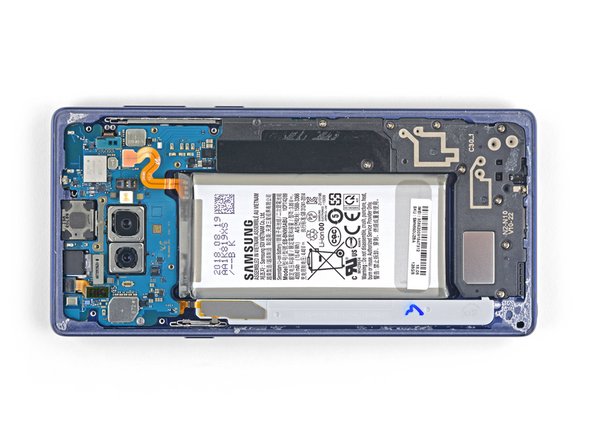
Peel the wireless charging coil off the battery starting with the left side.
-
-
Este passo não foi traduzido. Ajude a traduzi-lo
-
Use the tip of a spudger to disconnect the orange ribbon cable connecting the battery to the motherboard.
-
-
Este passo não foi traduzido. Ajude a traduzi-lo
-
Remove the nine 4 mm Phillips screws from the plastic cover next to the battery.
-
-
Este passo não foi traduzido. Ajude a traduzi-lo
-
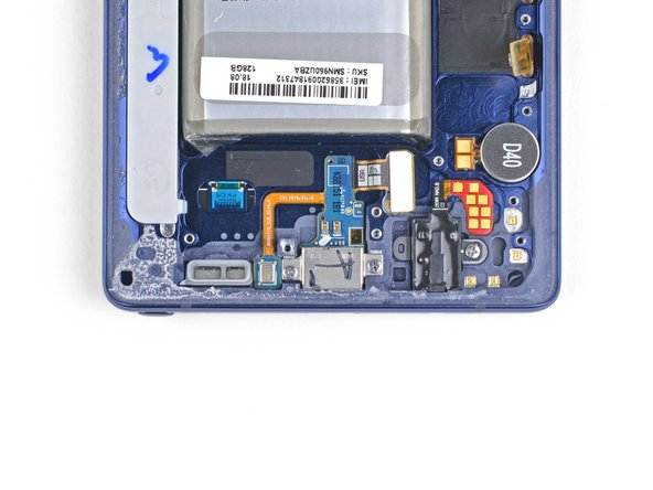
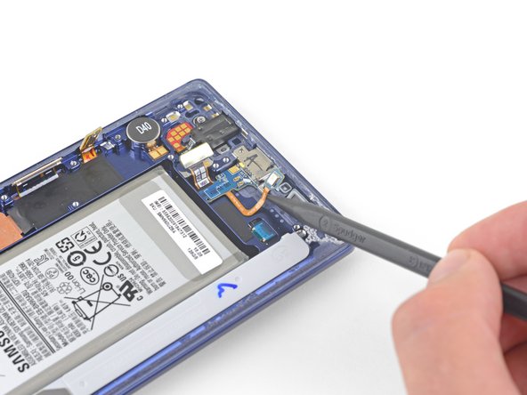
Insert the tip of a spudger into the top of the lower midframe.
-
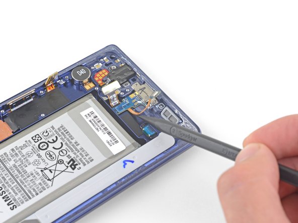
Pry the lower midframe out from the phone.
-
Remove the lower midframe.
-
-
Este passo não foi traduzido. Ajude a traduzi-lo
-
Use the tip of a spudger to pry the front camera connector straight up and out of its socket.
-
Use tweezers to remove the front camera.
-
-
Este passo não foi traduzido. Ajude a traduzi-lo
-
Use the tip of a spudger to disconnect the iris scanner from the motherboard.
-
Use tweezers to remove the iris scanner.
-
-
Este passo não foi traduzido. Ajude a traduzi-lo
-
Use the flat end of a spudger to pry the front sensor connector out of its socket.
-
-
Este passo não foi traduzido. Ajude a traduzi-lo
-
Use the flat end of a spudger to disconnect the display cable from the motherboard.
-
-
Este passo não foi traduzido. Ajude a traduzi-lo
-
Use the flat end of a spudger to disconnect the touchscreen cable from the motherboard.
-
-
Este passo não foi traduzido. Ajude a traduzi-lo
-
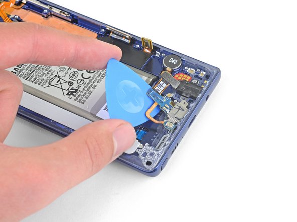
Use the flat end of a spudger to disconnect the charging assembly from the motherboard.
-
-
Este passo não foi traduzido. Ajude a traduzi-lo
-
Remove the three 4 mm Phillips screws securing the motherboard.
-
-
Este passo não foi traduzido. Ajude a traduzi-lo
-
Use a spudger to gently lift the motherbord from the upper-left corner.
-
Carefully remove the motherboard.
-
-
Este passo não foi traduzido. Ajude a traduzi-lo
-
Remove the two 3.2 mm Phillips screws from the charging assembly.
-
-
Este passo não foi traduzido. Ajude a traduzi-lo
-
Use the tip of a spudger to lift the microphone out from its housing and separate the microphone cable from the phone.
-
-
Este passo não foi traduzido. Ajude a traduzi-lo
-
Slide an opening pick underneath the charging assembly and pry to release it from the phone.
-
-
Este passo não foi traduzido. Ajude a traduzi-lo
-
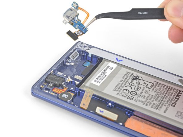
Use a pair of tweezers to remove the charging assembly.
-


Cancelar: não concluí este guia.
19 outras pessoas executaram este guia.

6 comentários
How do I put the back back on?
Hey William, thanks for the question! Check out the second bullet on step 13: To install a back cover:
Excellent guide.
After reassembling to step 17( reconnecting the battery) I tried powering on the phone. Nothing happened. I connected to a charger,, the phone vibrated and the red blinking light appeared. I left the phone connected to the charger for an hour, tried to power on and nothing happened. I checked to make sure all the connections were tight, but to no avail. I tried a soft reset, but that didn’t work either. Any idea what I did wrong?
Thank you!
Since there are signs of life when you turn on/charge the phone, but nothing on screen, here’s what I would try:
1. Disconnect the charger
2. Disconnect the battery cable from the motherboard
3. Disconnect the display cable from the motherboard
4. Reconnect the display cable
5. Reconnect the battery cable
6. Power on to test
If that does not fix it, another cable may not be properly connected. This sometimes prevents certain phones from powering on. Otherwise the display connector may have been damaged during the repair.