Esta versão pode conter edições incorretas. Mude para o último instantâneo verificado.
O que você precisa
-
Este passo não foi traduzido. Ajude a traduzi-lo
-
Before starting, ensure device is completely turned off.
-
On the back of phone, locate the slot on the top left corner.
-
Insert plastic opening tool or fingernail and pull up on the back plate.
-
With the corner released, slide your finger around the device between the back plate and the phone to release connectors.
-
-
Este passo não foi traduzido. Ajude a traduzi-lo
-
Insert fingernail into the slot on bottom of battery and gently pull up.
-
Remove the battery.
-
-
Este passo não foi traduzido. Ajude a traduzi-lo
-
Remove the 14 3.45 mm Phillips #000 screws from the assembly.
-
Gently, insert plastic opening tool into seam above the volume buttons of your phone.
-
-
-
Este passo não foi traduzido. Ajude a traduzi-lo
-
Slowly slide plastic opening tool around the device to release all the connectors internal to the device.
-
The device should easily come apart after the plastic opening tool is slid around the entire device.
-
-
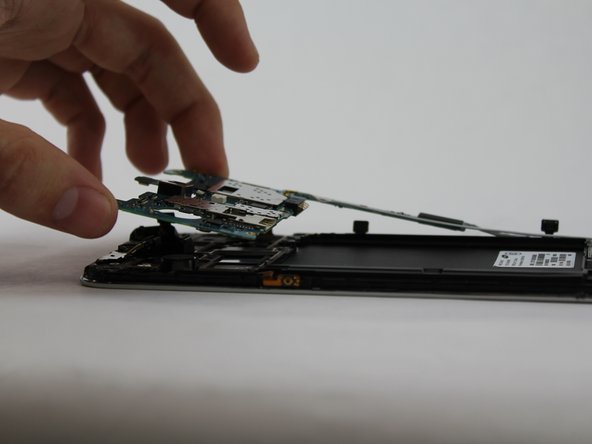
Este passo não foi traduzido. Ajude a traduzi-lo
-
Remove the 2.55 mm Phillips #000 screw from the motherboard panel.
-
-
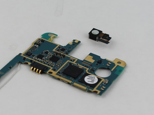
Este passo não foi traduzido. Ajude a traduzi-lo
-
On the back of the motherboard, remove the connector of the rear facing camera from the motherboard.
-
Camera is now detached from device.
-


Cancelar: não concluí este guia.
Uma outra pessoa concluiu este guia.
Equipe

USF Tampa, Team 17-2, Blackwell Winter 2016 Membro de USF Tampa, Team 17-2, Blackwell Winter 2016
USFT-BLACKWELL-W16S17G2
Membros da 4
Autoria de 8 guias