Esta versão pode conter edições incorretas. Mude para o último instantâneo verificado.
O que você precisa
-
Este passo não foi traduzido. Ajude a traduzi-lo
-
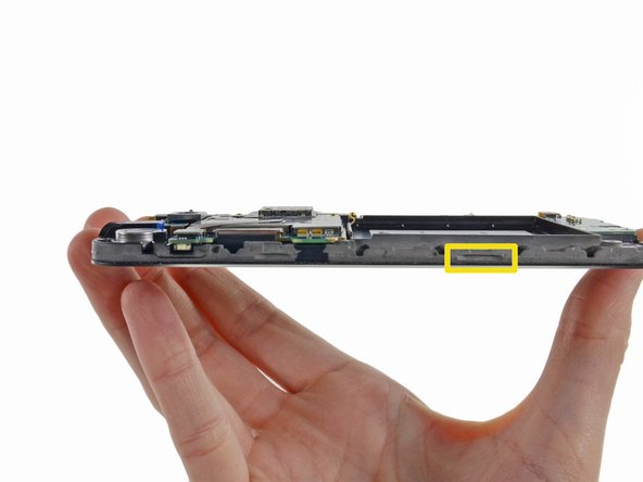
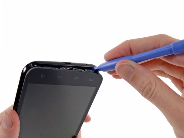
Insert a plastic opening tool, or your fingernail, into the opening near the left side of the headphone jack.
-
Pry the opening tool downward to pop the rear case from its clips securing it to the the midframe.
-
-
Este passo não foi traduzido. Ajude a traduzi-lo
-
Use the flat end of a spudger, or your fingernail, to press the microSD card slightly deeper into its slot until you hear a click.
-
After the click, release the card and it will pop out of its slot.
-
-
Este passo não foi traduzido. Ajude a traduzi-lo
-
Wedge a plastic opening tool into the crevice between the battery and midframe located near the bottom left corner.
-
Push the plastic opening tool downward to pry the battery up from its housing.
-
-
Este passo não foi traduzido. Ajude a traduzi-lo
-
Remove the six 4.0 mm Phillips #00 screws securing the midframe to the front panel assembly.
-
-
Este passo não foi traduzido. Ajude a traduzi-lo
-
The first insertion point is a divot to the left of the micro-USB port.
-
The second insertion point is a divot to the right of the micro-USB port near the corner of the phone.
-
The final insertion point is located about two inches to the right of the volume control toggle, toward the corner of the phone. An additional insertion point is located slightly to the right of the volume button if you need it.
-
-
-
Este passo não foi traduzido. Ajude a traduzi-lo
-
Insert a plastic opening tool slightly to the left of the micro-USB port, and pry between the midframe and the display to open a gap.
-
-
Este passo não foi traduzido. Ajude a traduzi-lo
-
Wedge a plastic opening tool slightly to the right of the micro-USB port, and pry between the midframe and the display to widen the gap.
-
-
Este passo não foi traduzido. Ajude a traduzi-lo
-
Pry again about two inches to the right of the volume control toggles between the midframe and the front panel assembly.
-
-
Este passo não foi traduzido. Ajude a traduzi-lo
-
Pull the micro-USB end of the front panel assembly out and away from the midframe and lift up to free it entirely.
-
-
Este passo não foi traduzido. Ajude a traduzi-lo
-
Headphone jack/vibrator assembly cable connector
-
Front-facing camera cable connector
-
Digitizer cable connector
-
Display cable connector
-
-
Este passo não foi traduzido. Ajude a traduzi-lo
-
Use the flat end of a spudger to disconnect the headphone jack/vibrator assembly cable.
-
-
Este passo não foi traduzido. Ajude a traduzi-lo
-
Use the flat end of a spudger to disconnect the front-facing camera cable connector.
-
-
Este passo não foi traduzido. Ajude a traduzi-lo
-
Use a spudger to disconnect the display cable connector.
-
-
Este passo não foi traduzido. Ajude a traduzi-lo
-
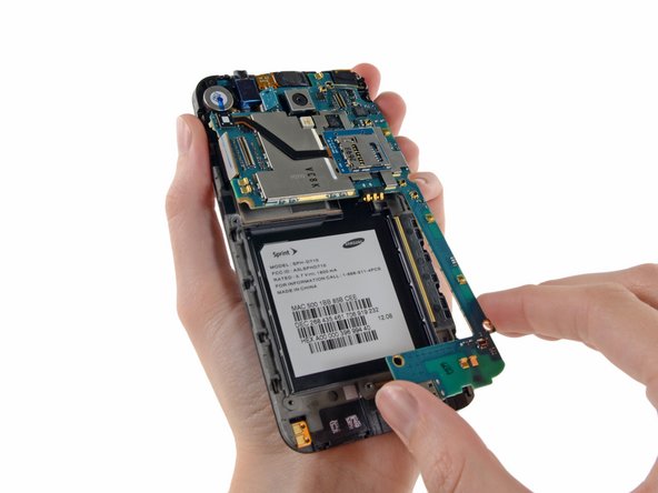
Lift the micro-USB end of the motherboard away from the display assembly and pull it down.
-
-
Este passo não foi traduzido. Ajude a traduzi-lo
-
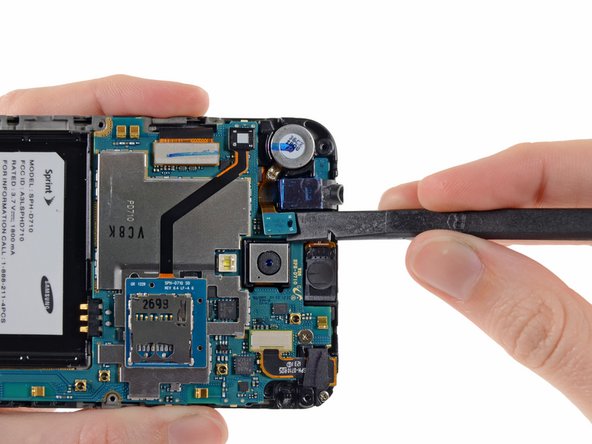
Remove the 2.3 mm Phillips #00 screw securing the front-facing camera bracket to the display assembly.
-
-
Este passo não foi traduzido. Ajude a traduzi-lo
-
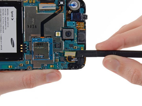
Remove the front-facing camera bracket from the display assembly.
-
-
Este passo não foi traduzido. Ajude a traduzi-lo
-
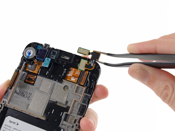
Using a pair of tweezers, or your fingers, remove the front-facing camera/earpiece speaker assembly.
-


Cancelar: não concluí este guia.
8 outras pessoas executaram este guia.
