Esta versão pode conter edições incorretas. Mude para o último instantâneo verificado.
O que você precisa
-
Este passo não foi traduzido. Ajude a traduzi-lo
-
Remove the screws on both sides and the bottom of the camera with the Phillips #00 screwdriver.
-
-
Este passo não foi traduzido. Ajude a traduzi-lo
-
Gently pry apart the rear casing from the body of the camera.
-
-
Este passo não foi traduzido. Ajude a traduzi-lo
-
Use the tweezers to gently peel the ribbon from the contents inside of the camera, leaving it connected to the rear casing.
-
Set aside rear casing.
-
-
Este passo não foi traduzido. Ajude a traduzi-lo
-
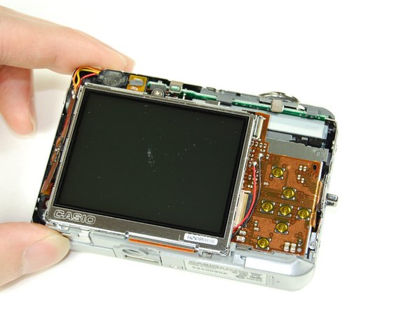
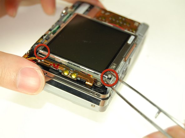
Use the tweezers to pry the LCD screen from the frame.
-
-
-
Este passo não foi traduzido. Ajude a traduzi-lo
-
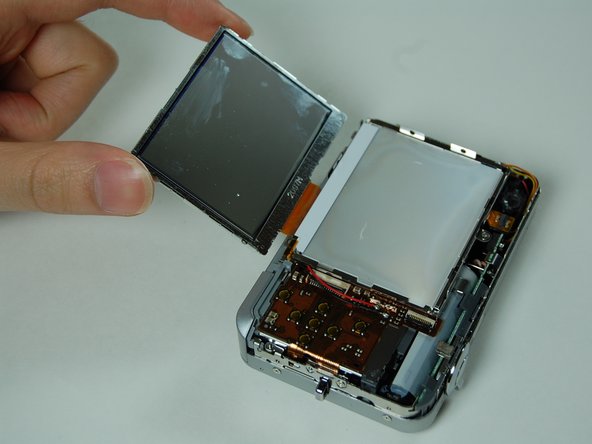
Use the tweezers to flip the LCD screen to the other side.
-
-
Este passo não foi traduzido. Ajude a traduzi-lo
-
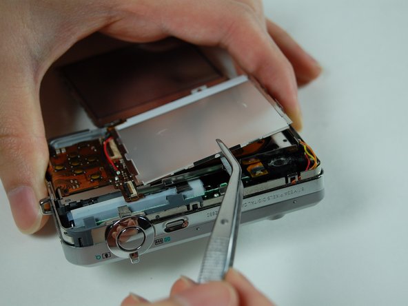
Pry the LCD casing from the tape that is underneath it and then flip it to the opposite side to expose the contents under it.
-
-
Este passo não foi traduzido. Ajude a traduzi-lo
-
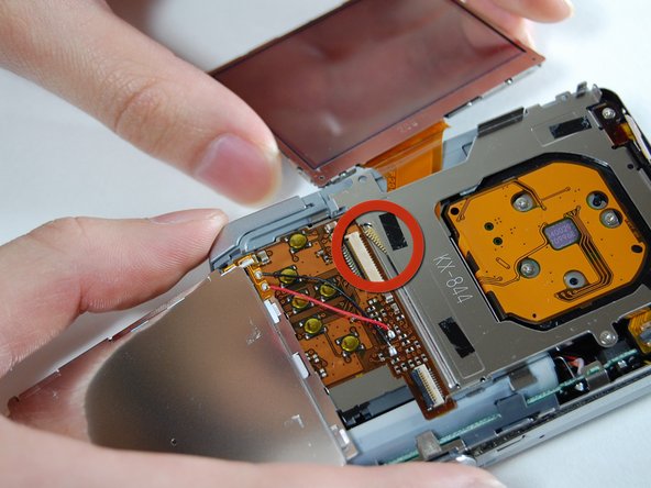
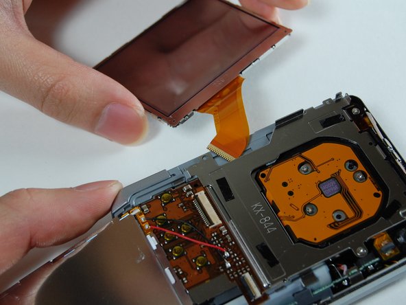
Use the tweezers to flip open the connector that is holding the ribbon connected to the LCD screen in place.
-
Remove the LCD screen with the ribbon from the camera.
-
-
Este passo não foi traduzido. Ajude a traduzi-lo
-
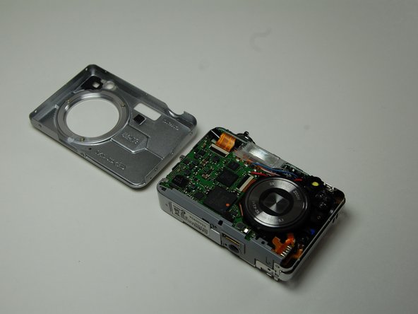
Remove the front casing from the body of the camera.
-
-
Este passo não foi traduzido. Ajude a traduzi-lo
-
Remove two screws on the side where the battery is located using the Phillips #00 screwdriver.
-
Pull the side casing so it becomes dislocated from the top of the camera frame.
-
-
Este passo não foi traduzido. Ajude a traduzi-lo
-
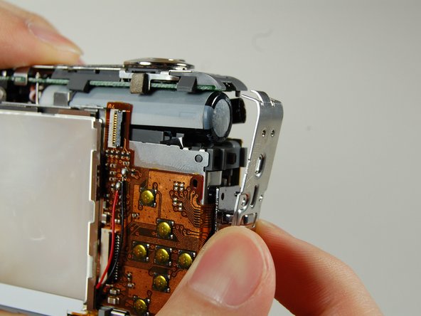
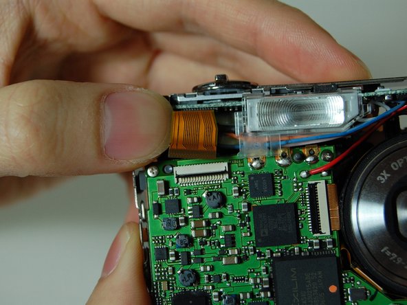
On the front of the camera, near the flash flip, there is a connector holding a ribbon. Remove the ribbon from the connector.
-
-
Este passo não foi traduzido. Ajude a traduzi-lo
-
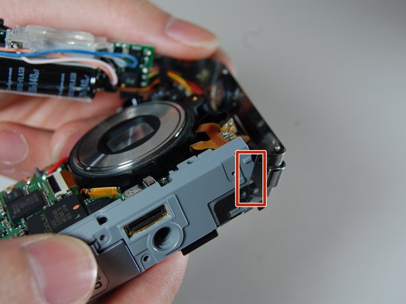
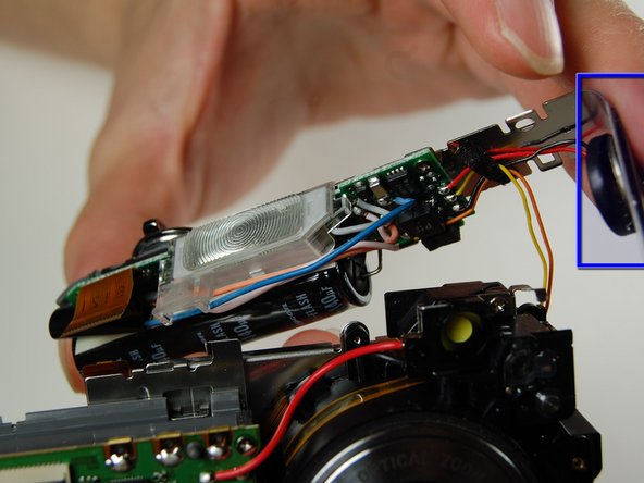
Carefully remove the L shaped frame from the camera by popping the frame off the bumps and tabs located at the bottom of the camera.
-
The blue box is the speaker.
-


Equipe

Cal Poly, Team 4-38, Regan Winter 2011 Membro de Cal Poly, Team 4-38, Regan Winter 2011
CPSU-REGAN-W11S4G38
Membros da 4
Autoria de 13 guias