Esta versão pode conter edições incorretas. Mude para o último instantâneo verificado.
O que você precisa
-
Este passo não foi traduzido. Ajude a traduzi-lo
-
The battery is accessible through the back of the drone.
-
Press the tabs on both sides of the white stripe to pull the battery out.
-
-
Este passo não foi traduzido. Ajude a traduzi-lo
-
Remove the screws starting with the three smaller ones on the top part of the battery.
-
Remove the three screws on the other side.
-
There are two screws tucked under where the yellow circle is located. You will need to remove the other screws first before you get to these two.
-
-
Este passo não foi traduzido. Ajude a traduzi-lo
-
Remove the top piece, and gently pry the two halves apart. Divide the sticker if necessary.
-
-
-
Este passo não foi traduzido. Ajude a traduzi-lo
-
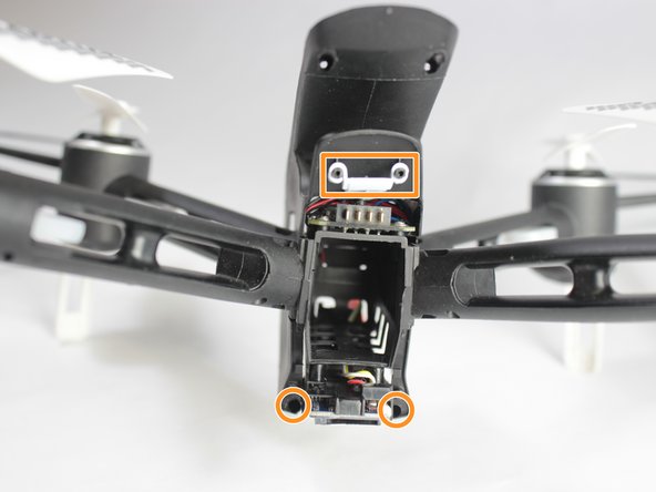
Remove the 4x 7mm screws on the top and bottom, and the 2x 5mm screws from the middle, then remove the back part of the housing.
-
Remove the two hidden screws at the bottom, and the white power button.
-
-
Este passo não foi traduzido. Ajude a traduzi-lo
-
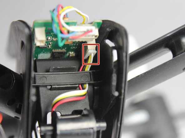
Unplug all the cords from the circuit boards.
-
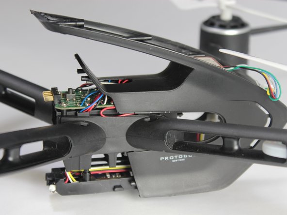
Carefully slide the main body right off the arms.
-
-
Este passo não foi traduzido. Ajude a traduzi-lo
-
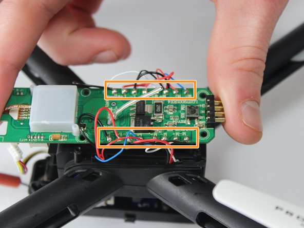
Remove the four 4mm Phillips screws.
-
Desolder all cords on the circuit board, and pull the board up and out.
-


Cancelar: não concluí este guia.
Uma outra pessoa concluiu este guia.
Equipe

UW Stout, Team S8-G6, Ogden Spring 2018 Membro de UW Stout, Team S8-G6, Ogden Spring 2018
UWSTOUT-OGDEN-S18S8G6
Membros da 3
Autoria de 4 guias