Esta versão pode conter edições incorretas. Mude para o último instantâneo verificado.
O que você precisa
-
Este passo não foi traduzido. Ajude a traduzi-lo
-
Orient the computer so that the side with the line of screws on it is away from you.
-
Use your thumbs to push both battery release tabs away so that the edge of the battery lifts up.
-
Lift the battery out of the computer.
-
-
Este passo não foi traduzido. Ajude a traduzi-lo
-
Remove the three identical Phillips screws from the memory door.
-
-
Este passo não foi traduzido. Ajude a traduzi-lo
-
Lift the memory door up enough so that you can get a grip on it, and slide it toward you, pulling it away from the casing.
-
-
Este passo não foi traduzido. Ajude a traduzi-lo
-
Release the tabs on each side of the RAM chip at the same time. These tabs lock the chip in place and releasing them will cause the chip to "pop" up.
-
Pull the chip directly out from its connectors. If there is a second RAM chip installed, pop it out in the same manner.
-
-
Este passo não foi traduzido. Ajude a traduzi-lo
-
1) With your fingernails, grasp the locking bar on either side slide it a small amount (about 1/16" or 2 mm) towards the battery.
-
2) After disengaging the locking bar, slide the cable out of the connector.
-
-
Este passo não foi traduzido. Ajude a traduzi-lo
-
Loosen the trackpad connector by pulling the locking bar toward the battery housing, using the tips of your fingers.
-
Slide the trackpad cable out of the loosened connector.
-
Note: When reassembling the case, the trackpad cable can get stuck below the slot to the motherboard. It's possible to nudge it out slowly by gently prodding it on either side with a small screwdriver. You don't need to use much force to do this. Eventually it will just pop back out and you can reconnect as per the instructions above. Also, note that the locking bar comes loose so if you see a little piece of plastic lying around when reassembling, that's what it is. :)
-
-
Este passo não foi traduzido. Ajude a traduzi-lo
-
Remove the following 10 screws from the bottom case:
-
Three 1.7 mm Phillips from the front edge of the battery compartment.
-
One 3.9 mm T8 Torx to the right of the memory card.
-
One 6.9 mm T8 Torx at the left edge of the memory compartment.
-
Three 12.4 mm fully threaded Phillips from the center of the row of screws along the back edge of the case.
-
Two 15.1 mm 2.5 mm threaded Phillips, one from either end of the row of screws along the back edge of the case.
-
-
Este passo não foi traduzido. Ajude a traduzi-lo
-
Turn the computer over and rotate it so that the DVI port faces you.
-
Remove the four identical Phillips screws spread along this edge of the case.
-
-
-
Este passo não foi traduzido. Ajude a traduzi-lo
-
Turn the computer 180 degrees so that the power receptacle faces you, and remove the four Phillips screws (identical to those in the last step).
-
-
Este passo não foi traduzido. Ajude a traduzi-lo
-
Open the computer and turn it so that the screen faces you.
-
Pull the upper case off, lifting from the back, and working around the edges.
-
-
Este passo não foi traduzido. Ajude a traduzi-lo
-
Use a spudger to loosen the casing if it sticks.
-
Once the casing is entirely free, lift it off of the computer.
-
-
Este passo não foi traduzido. Ajude a traduzi-lo
-
Use the method described in the step for disconnecting the keyboard ribbon to loosen the connector on the DC-In board.
-
Pull the cable free of the loosened connector.
-
-
Este passo não foi traduzido. Ajude a traduzi-lo
-
Remove the single Phillips screw from the Bluetooth board.
-
-
Este passo não foi traduzido. Ajude a traduzi-lo
-
Lift the Bluetooth board partially out of the computer and disconnect the attached antenna cable.
-
-
Este passo não foi traduzido. Ajude a traduzi-lo
-
Disconnect the black speaker cable from the sound board.
-
-
Este passo não foi traduzido. Ajude a traduzi-lo
-
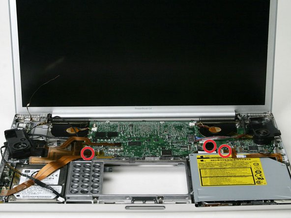
Remove the single T8 Torx screw from the left speaker assembly.
-
-
Este passo não foi traduzido. Ajude a traduzi-lo
-
Disconnect the orange DC-In cable from the logic board.
-
-
Este passo não foi traduzido. Ajude a traduzi-lo
-
Deroute the cables from the right side of the speaker and lift it off of the logic board.
-
-
Este passo não foi traduzido. Ajude a traduzi-lo
-
Remove the single T8 Torx screw from the right speaker assembly.
-
-
Este passo não foi traduzido. Ajude a traduzi-lo
-
Deroute the display data cable from the left side of the speaker and pull the speaker assembly off the logic board.
-
-
Este passo não foi traduzido. Ajude a traduzi-lo
-
In order to disconnect the speaker cable from the front edge of the logic board, you must disconnect the sound cable, the optical drive cable, and the PRAM battery cable.
-
-
Este passo não foi traduzido. Ajude a traduzi-lo
-
Deroute the speaker cable from the front edge of the logic board.
-


Cancelar: não concluí este guia.
Uma outra pessoa concluiu este guia.
