Esta versão pode conter edições incorretas. Mude para o último instantâneo verificado.
O que você precisa
-
Este passo não foi traduzido. Ajude a traduzi-lo
-
Use a coin or a spudger to turn the battery locking screw 90 degrees clockwise.
-
Lift the battery out of the computer.
-
-
Este passo não foi traduzido. Ajude a traduzi-lo
-
Open the computer with the display facing you and rotate the display back as far as possible.
-
Remove the T6 Torx screw from the bottom left corner of the display assembly. The computer casing will not allow the screwdriver to be inserted directly into the screw, so be careful not to strip the screw.
-
-
Este passo não foi traduzido. Ajude a traduzi-lo
-
Remove the T6 Torx screw from the bottom right corner of the display assembly.
-
-
Este passo não foi traduzido. Ajude a traduzi-lo
-
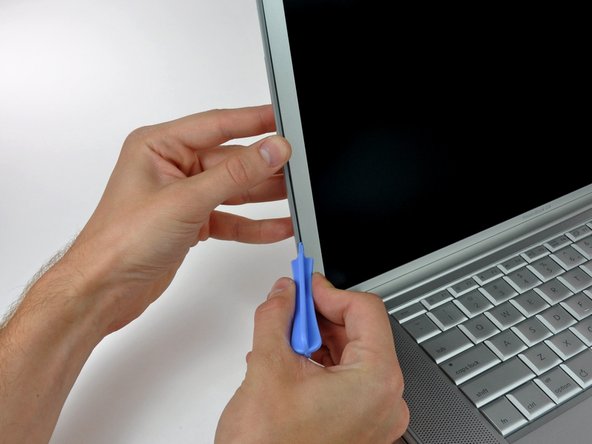
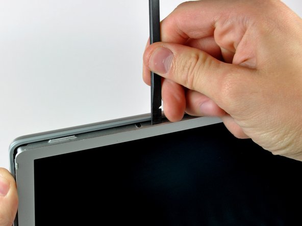
Insert a plastic opening tool between the left edge of the front display bezel and the plastic strip attached to the rear bezel, with the edge of the tool angled toward the LCD.
-
Rotate the tool away from the LCD to pop the rear bezel off the tabs on the front display bezel.
-
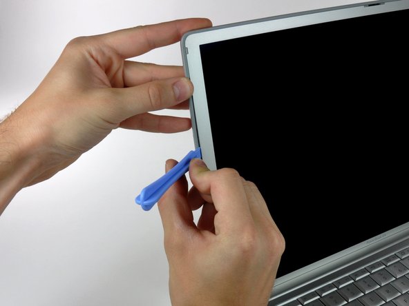
Work along the left edge of the display until the rear bezel is evenly separated from the front bezel.
-
-
Este passo não foi traduzido. Ajude a traduzi-lo
-
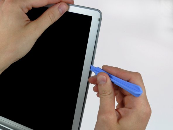
Insert a plastic opening tool between the right edge of the front display bezel and the plastic strip attached to the rear bezel, with the edge of the tool angled toward the LCD.
-
Rotate the tool away from the LCD to pop the rear bezel off the tabs on the front display bezel.
-
Work along the right edge of the display until the rear bezel is evenly separated from the front bezel.
-
-
-
Este passo não foi traduzido. Ajude a traduzi-lo
-
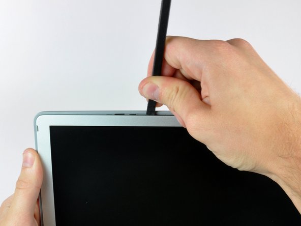
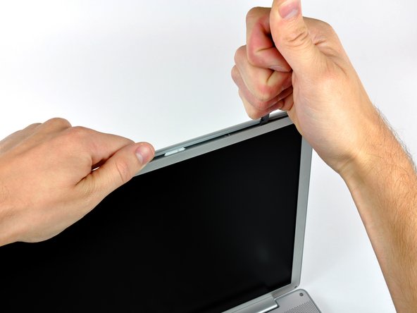
Insert a spudger just to the left of the hinge opening on the top edge of the display between the front display bezel and the plastic strip attached to the rear bezel.
-
Pry the rear bezel away from the front bezel along the top left half of the display.
-
-
Este passo não foi traduzido. Ajude a traduzi-lo
-
Insert a spudger just to the right of the hinge opening on the top edge of the display between the front display bezel and the plastic strip attached to the rear bezel.
-
Pry the rear bezel away from the front bezel along the top right half of the display.
-
-
Este passo não foi traduzido. Ajude a traduzi-lo
-
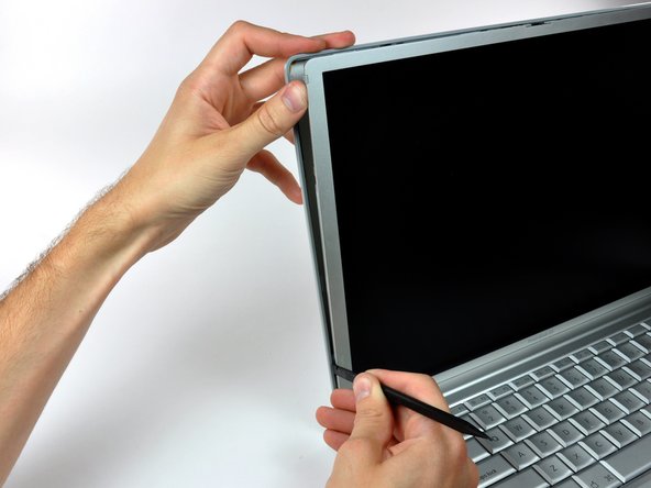
Now that the top edge is released, use a spudger to completely release the clips along the left edge of the display.
-
-
Este passo não foi traduzido. Ajude a traduzi-lo
-
Use a spudger to release the clips along the right edge of the display.
-
-
Este passo não foi traduzido. Ajude a traduzi-lo
-
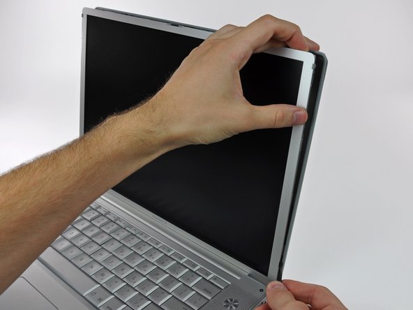
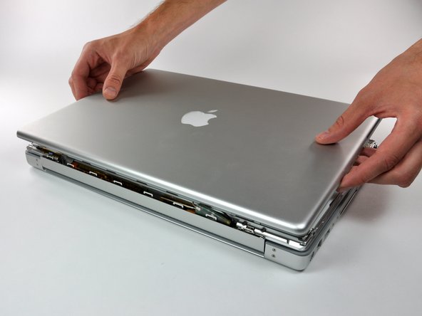
Close the display.
-
Rotate the top edge of the rear display bezel slightly away from the rest of the display, and then lift the lower edge of the rear bezel away from the clutch cover.
-
-
Este passo não foi traduzido. Ajude a traduzi-lo
-
Carefully lift the antenna board out of the clutch assembly.
-
Peel the three self-adhesive flaps off the plastic cover on the underside of the antenna board.
-
Remove the protective plastic cover from the antenna board.
-
-
Este passo não foi traduzido. Ajude a traduzi-lo
-
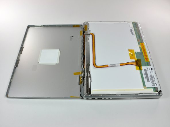
Use the flat end of a spudger to disconnect both antenna connectors from the antenna board.
-
The rear bezel can now be completely removed from the LCD assembly.
-
-
Este passo não foi traduzido. Ajude a traduzi-lo
-
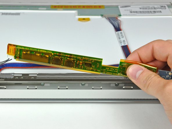
Using the tip of a spudger, raise the inverter out from the clutch cover.
-
Lift the inverter enough to reveal both cable connectors.
-
Lift the inverter enough to reveal both cable connectors.
-
-
Este passo não foi traduzido. Ajude a traduzi-lo
-
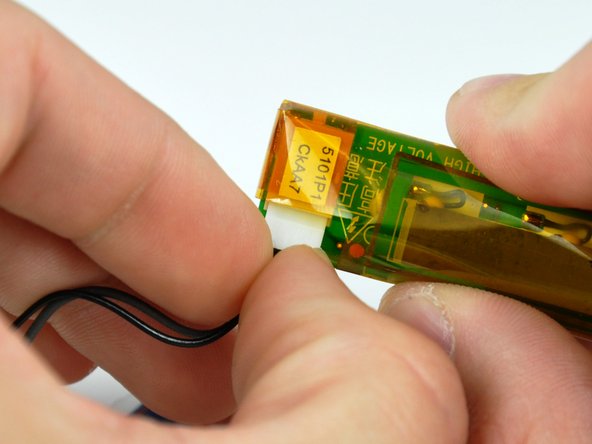
Disconnect both inverter cables by pulling their connectors away from the sockets on the inverter board.
-
Remove the inverter from the display.
-


Cancelar: não concluí este guia.
4 outras pessoas executaram este guia.
