Esta versão pode conter edições incorretas. Mude para o último instantâneo verificado.
O que você precisa
-
Este passo não foi traduzido. Ajude a traduzi-lo
-
Remove all the cables, including the power cables before opening the unit.
-
-
Este passo não foi traduzido. Ajude a traduzi-lo
-
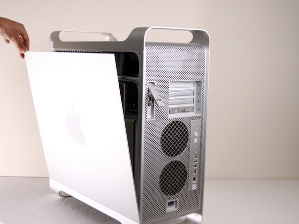
Remove the air deflector (the clear plastic cover) by pulling on the handle.
-
-
Este passo não foi traduzido. Ajude a traduzi-lo
-
Pull the fan assembly out; it should slide out easily.
-
-
Este passo não foi traduzido. Ajude a traduzi-lo
-
The cooling fan unit is located on the bottom right of the Apple G5 Desktop.
-
-
Este passo não foi traduzido. Ajude a traduzi-lo
-
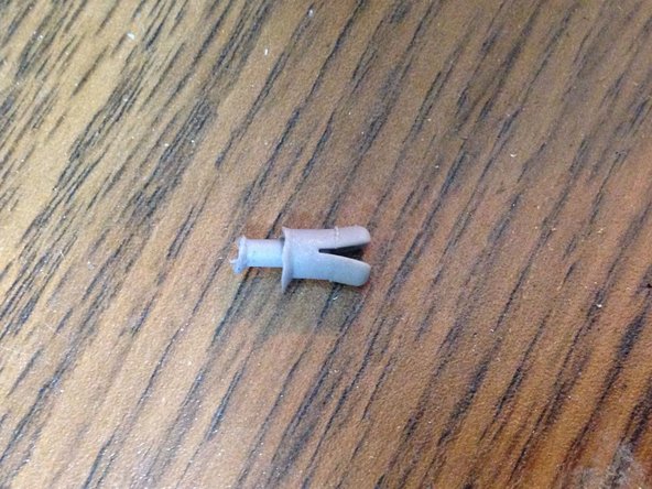
Remove the G5 metal cover from the processing/cooling unit of the computer. NOTE: Apple inserted a rather fragile plastic pin that inserts through the top divider shield and clips into a tab on the hidden ledge of this CPU shield. Removing this pin, certainly voided Mac's warranty - but more appropriate for now, voids most after-market insurance plans. A replacement pin (new) is hard to get ahold of, and very few are talented and patient enough to remove this pin without damaging it. Just something to keep in mind. If you have no warranty any longer or don't care, please continue...
-
Pull the metal plate to the left and outward to remove the plate from the processing/cooling unit.
-
-
-
Este passo não foi traduzido. Ajude a traduzi-lo
-
Unplug the fan's power cable from the upper rightmost corner of the motherboard (connection J45). If there is a video card in place, carefully pull the cable plug down between the back edge of the video card and the motherboard. Note, the photo shows the unplugged cable and the area it plugs into outlined in yellow. No video card is shown in this photo.
-
-
Este passo não foi traduzido. Ajude a traduzi-lo
-
Locate the tabs on the fan unit.
-
While pushing in on the tabs, highlighted in yellow, pull the fan back towards the cooling unit.
-
-
Este passo não foi traduzido. Ajude a traduzi-lo
-
After removal of the bottom right fan the space should look like this.
-
-
Este passo não foi traduzido. Ajude a traduzi-lo
-
Locate the Cooling Unit on the Apple G5.
-
Put the CPU case on its back with the opening facing up to make the next steps easier.
-
-
Este passo não foi traduzido. Ajude a traduzi-lo
-
Unscrew 8 T10 screws from the cooling unit. NOTE: these screws are acctually allen keys. The prefered tool will be long handled allen keys. t10 are 2.74mm (closest allen key is 2.5 or 3mm) and t15 are 3.27mm(closest allen key is 3mm and 4mm). You may strip your tool or the actual screws themselves. Use a set of high quality long handled allen keys.
-
The screws will loosen but will not come out, they are designed to loosen the unit, but remain in place.
-
The last two images show another version of the LCS (out of the computer) in the G5 with off-center views to show the 8 screw holes.
-
-
Este passo não foi traduzido. Ajude a traduzi-lo
-
Pull the cooling/processing unit straight up to prevent damage to logic board
-
The sleeves around the 6 screws may hold it in, if so just take a pair of needle nose pliers and gently squeeze the sleeves until it releases.
-
Pull the bottom, then side towards the bottom of the CPU case, first to move around the bottom coolant sleeve around the heat sinking bracket. *heat sinking bracket not in picture*
-
-
Este passo não foi traduzido. Ajude a traduzi-lo
-
NOTE: Here are the standoffs without the cooling unit installed to make it easier to understand where the screws are located. Remove the bottom 2 standoffs so it is easier to remove the power supply.
-
Check the pin connections for any damage. All the pins highlighted in yellow should appear straight up and not appear bent. DON'T TOUCH THE PINS. A bent pin will result in your computer not powering on.
-
-
Este passo não foi traduzido. Ajude a traduzi-lo
-
Locate the power supply in the Apple G5 computer. It is located under the metal plate at the bottom of the computer case.
-
-
Este passo não foi traduzido. Ajude a traduzi-lo
-
Undo the clip shown by pulling up on the edge closest to the RAM slots.
-
Unplug the black rectangular plug with a rounded top by pulling outwards.
-
-
Este passo não foi traduzido. Ajude a traduzi-lo
-
Undo the clip shown by pulling up on the edge.
-
Unplug the cord that is located below where the cooling unit was. To do this, pull outwards.
-
-
Este passo não foi traduzido. Ajude a traduzi-lo
-
Remove the 2 Philips screws holding the power supply cover on.
-
-
Este passo não foi traduzido. Ajude a traduzi-lo
-
Remove the 4 Philips screws on the underside of the computer case.
-
-
Este passo não foi traduzido. Ajude a traduzi-lo
-
Unplug the final cable attached to the power supply from the computer.
-
Now the power supply should come out of the computer freely.
-
-
Este passo não foi traduzido. Ajude a traduzi-lo
-
The bottom of the computer should look like this when removal of the power supply is complete.
-


Cancelar: não concluí este guia.
73 outras pessoas executaram este guia.
Equipe

Cal Poly, Team 5-8, Forte Winter 2010 Membro de Cal Poly, Team 5-8, Forte Winter 2010
CPSU-FORTE-W10S5G8
Membros da 7
Autoria de 20 guias
12 comentários
I followed this guide to replace the PSU in my 2x2.0 PCI G5 - it now works great. I'd like to add that my machine didn't boot right away, I needed to reset the SMU on the main Logic board several times and I also re-seated the RAM chips which seemed to cajole the old beast back into life. I replaced a 450W PSU with a 600W and all seems well so far. Many thanks to the team for posting this ifixit guide.
these Apple support notes are worth a look if you run into problems restarting a machine:
http://support.apple.com/kb/HT2652?viewl...
and
Finally - I would also like to add that this guide shows the CPU unit of what I think is one of the crazy liquid-cooled G5s that made a brief appearance in the Powermac range. The same steps still apply for the more common air-cooled models. The only difference being that my machine's CPU units were secured on their mountings with Allen-key type screws - not Torx screws. Doing this repair was not as difficult as you might think, I managed fine and I'm not a tech specialist.