Esta versão pode conter edições incorretas. Mude para o último instantâneo verificado.
O que você precisa
-
Este passo não foi traduzido. Ajude a traduzi-lo
-
There is a screw under the shiny UL sticker. Remove the sticker and screw to remove this bottom panel.
-
-
Este passo não foi traduzido. Ajude a traduzi-lo
-
Flipping the light upside down will present a small section of the bezel that can be pried upward. It is a small plastic strip with hooks that have to be disengaged to be removed.
-
-
-
Este passo não foi traduzido. Ajude a traduzi-lo
-
We can finally unscrew two more Philips head screws to remove the button ring.
-
-
Este passo não foi traduzido. Ajude a traduzi-lo
-
Now the screws holding the front screen shield need to be removed and the shield can be pulled away to the front.
-
Unscrew the four screws holding the inner screen assembly in place.
-
-
Este passo não foi traduzido. Ajude a traduzi-lo
-
The inner screen assembly can be pulled out slightly to reveal tabs on each side that hold the assembly in.
-
Pry the back tabs inwards to release.
-
-
Este passo não foi traduzido. Ajude a traduzi-lo
-
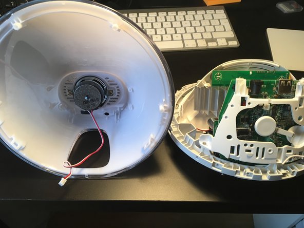
The screen is connected to the plastic domed back with holes. There are two screws at the back of the base of this domed panel. Remove screws to remove screen.
-


Cancelar: não concluí este guia.
41 outras pessoas executaram este guia.

13 comentários
Awesome teardown except for one little thing…
The factory sticker shows this is a 3530 which may not be different from a 3520. However, the bottom plate screw MUST be removed in order to separate the two halves. It is a little confusing saying “The bottom panel does not help gaining access to more screws. See next step.” I took that as being unnecessary, so skip.
I was able to fix my speaker inside it i got this alarm at a thrift store for cheap turns out the one wire just needed a better conenction to get working thank you for the steps to get to it
The first photo of step 5 is a little misleading, it looks like you are unscrewing something, it made me look for the screws
Other than that this was very helpful, thank you