Esta versão pode conter edições incorretas. Mude para o último instantâneo verificado.
O que você precisa
-
Este passo não foi traduzido. Ajude a traduzi-lo
-
Remove the four 3.4 mm screws from the right and left sides of your Panasonic Lumix Camera.
-
Remove the two 2.6 mm screws located next to the battery.
-
-
Este passo não foi traduzido. Ajude a traduzi-lo
-
Use the plastic opening tool to lift off the rear cover of your device. Go gently to avoid breaking anything.
-
The easiest place to open your device is from the HDMI port.
-
-
Este passo não foi traduzido. Ajude a traduzi-lo
-
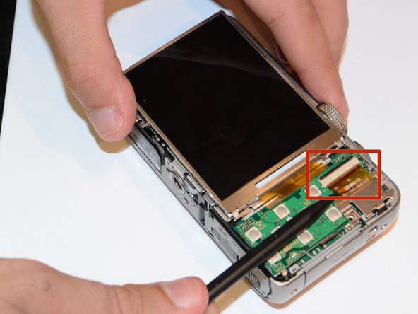
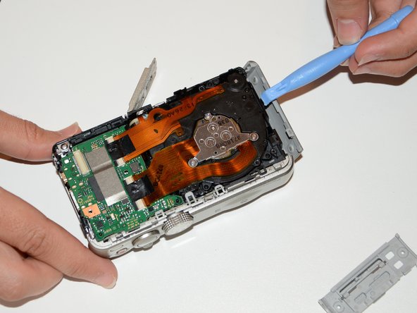
Use a spudger to lift the LCD ribbon cable locking bar by angling it up, then withdraw the ribbon.
-
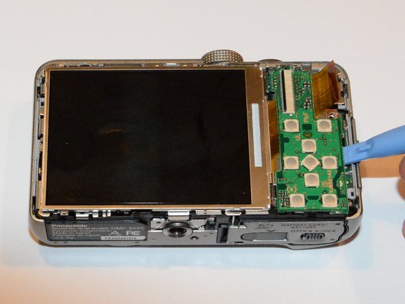
Use the plastic opening tool at the bottom right hand side of the button board to lift it up and out.
-
The buttons board comes out with a "click" as it snaps out of a connector below.
-
-
Este passo não foi traduzido. Ajude a traduzi-lo
-
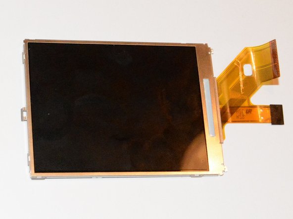
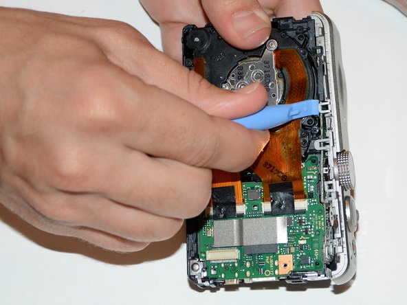
The LCD is retained by a clip on the left hand side, which you can release with a plastic opening too.
-
Lift the LCD from the left hand side, disengaging it at the right hand side from two small tabs.
-
-
-
Este passo não foi traduzido. Ajude a traduzi-lo
-
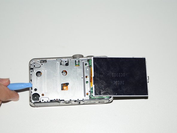
Remove the two 4.2 mm screws in order to remove the inner cover located beneath the screen.
-
Having removed the screws, use the plastic opening tool to lift off the inner cover, releasing it from clips on the top and bottom edges.
-
-
Este passo não foi traduzido. Ajude a traduzi-lo
-
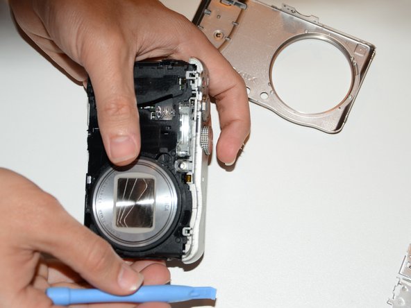
Remove the side covers using the plastic opening tool.
-
-
Este passo não foi traduzido. Ajude a traduzi-lo
-
After removing the side covers, you will be able to pull off the front cover.
-
-
Este passo não foi traduzido. Ajude a traduzi-lo
-
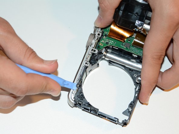
To remove the top cover, you need to remove a 3.7 mm screw as shown.
-
-
Este passo não foi traduzido. Ajude a traduzi-lo
-
Release the top cover by lifting several tabs with the plastic opening tool. Go gently to avoid breaking them.
-
-
Este passo não foi traduzido. Ajude a traduzi-lo
-
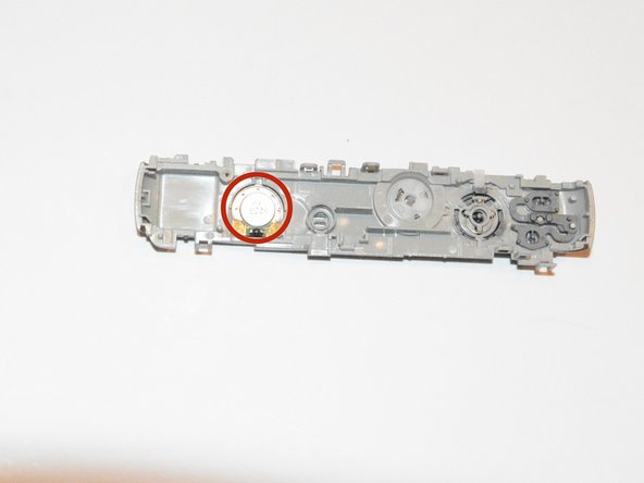
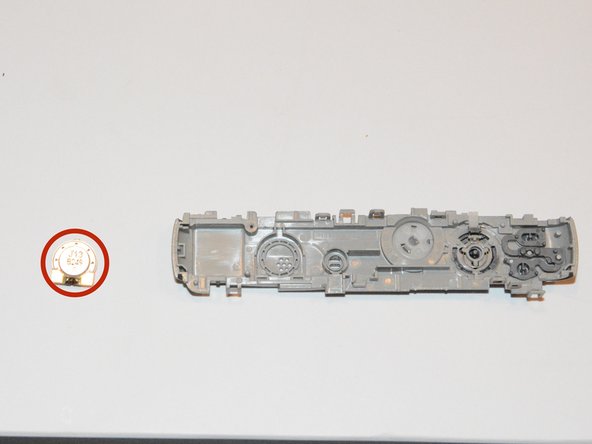
With the top cover removed the speaker can be very easily removed or replaced.
-


Equipe

USF Tampa, Team 9-5, Brown Winter 2015 Membro de USF Tampa, Team 9-5, Brown Winter 2015
USFT-BROWN-W15S9G5
Membros da 3
Autoria de 7 guias
Um comentário
In step 5, comparing it with the similar DMC-TZ35 I rather think there should be 3 screws, not 2. A 3rd hole can be seen at the bottom.