Esta versão pode conter edições incorretas. Mude para o último instantâneo verificado.
O que você precisa
-
Este passo não foi traduzido. Ajude a traduzi-lo
-
Remove both of the 3 mm screws on the bottom of the camera connected to the side panel.
-
-
Este passo não foi traduzido. Ajude a traduzi-lo
-
Remove the remaining 3 mm screw holding on the side panel and remove the panel entirely.
-
-
-
Este passo não foi traduzido. Ajude a traduzi-lo
-
On the opposite side of the camera, remove the two 3 mm screws.
-
Remove the bottom side panel and place it with its respective 3 mm screw.
-
-
Este passo não foi traduzido. Ajude a traduzi-lo
-
Remove the front panel (the panel around the lens casing) from the camera.
-
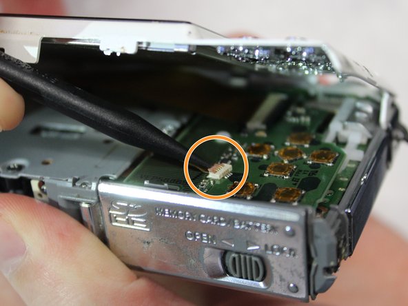
Remove the two ribbon cables connected to the back panel (the panel this the LCD screen) by lifting up on their respective tabs and gently pulling out the cord.
-
Remove the back panel from the camera.
-
-
Este passo não foi traduzido. Ajude a traduzi-lo
-
Remove the top control panel (connected to the flash battery) from the camera.
-


