Esta versão pode conter edições incorretas. Mude para o último instantâneo verificado.
O que você precisa
-
Este passo não foi traduzido. Ajude a traduzi-lo
-
Place the PSP face down and locate the battery cover on the left side of the device.
-
Lift and remove the battery cover to reveal the battery.
-
Remove the battery.
-
-
Este passo não foi traduzido. Ajude a traduzi-lo
-
Peel back the warranty sticker that is behind the battery with a spudger or your fingernail.
-
-
Este passo não foi traduzido. Ajude a traduzi-lo
-
Unscrew all four screws from the back of the PSP with the Phillips #00 Screwdriver.
-
Two are located behind the battery's warranty sticker.
-
Two are located on the right side of the PSP.
-
-
Este passo não foi traduzido. Ajude a traduzi-lo
-
Next, unscrew the two screws located at the top of the PSP.
-
-
Este passo não foi traduzido. Ajude a traduzi-lo
-
Then, remove the single screw from the bottom edge of the PSP (which is positioned next to the barcode).
-
-
Este passo não foi traduzido. Ajude a traduzi-lo
-
Slide the spudger in between the outer casing of the PSP, beginning at the "R" shoulder button, and gently pry off the casing.
-
Remove the front casing completely.
-
-
Este passo não foi traduzido. Ajude a traduzi-lo
-
Push the homebar to the right to release the tab located on the right side of the LCD screen.
-
-
Este passo não foi traduzido. Ajude a traduzi-lo
-
Slowly lift the LCD screen off the PSP starting at the top edge corner.
-
-
Este passo não foi traduzido. Ajude a traduzi-lo
-
Flip the small brown locks on the four ribbon cable connectors up using a spudger or fingernail.
-
Pull all four ribbon cables out.
-
Now remove the LCD screen and homebar from the PSP.
-
-
Este passo não foi traduzido. Ajude a traduzi-lo
-
Remove the metal tab that lies above the LCD screen.
-
-
Este passo não foi traduzido. Ajude a traduzi-lo
-
Remove the white plastic piece that holds the 'L' trigger in place.
-
-
-
Este passo não foi traduzido. Ajude a traduzi-lo
-
Remove the white plastic piece that holds the 'R' trigger in place.
-
-
Este passo não foi traduzido. Ajude a traduzi-lo
-
Remove the screw from the bottom left edge of the PSP.
-
-
Este passo não foi traduzido. Ajude a traduzi-lo
-
Being careful not to break the ribbon cable, use the spudger to peel the adhesive button of the the 'L' trigger off the PSP.
-
-
Este passo não foi traduzido. Ajude a traduzi-lo
-
Using a fingernail or spudger, flip up the retaining bracket on the d-pad and 'L' trigger ribbon cable.
-
Lift the black plastic bracket along with the d-pad contact pad, disconnecting the ribbon cable as you lift.
-
-
Este passo não foi traduzido. Ajude a traduzi-lo
-
Remove the cable from the connector and remove the entire black piece from the PSP.
-
-
Este passo não foi traduzido. Ajude a traduzi-lo
-
Remove the screw holding the analog stick in place.
-
-
Este passo não foi traduzido. Ajude a traduzi-lo
-
Flip up the lock on the analog sticks ribbon cable.
-
Remove the analog stick from the PSP.
-
-
Este passo não foi traduzido. Ajude a traduzi-lo
-
After removing the LCD Screen, the Button Pad should be easy to remove.
-
-
Este passo não foi traduzido. Ajude a traduzi-lo
-
Flip up the lock and detach the ribbon cable above the power jack.
-
-
Este passo não foi traduzido. Ajude a traduzi-lo
-
Carefully bend back the black tab holding the power jack in place and start pulling the jack up to release it from this clip.
-
-
Este passo não foi traduzido. Ajude a traduzi-lo
-
Pull the plug connecting the power jack to the motherboard.
-
Remove the power jack.
-
-
Este passo não foi traduzido. Ajude a traduzi-lo
-
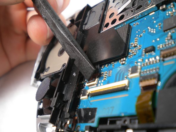
The speaker is spring loaded, so be sure to keep an eye on it in case it starts doing flips into the air when you push the tab. Be careful not to lose or damage it!
-
-
Este passo não foi traduzido. Ajude a traduzi-lo
-
Remove the cable carefully by lifting upwards from port attached to the motherboard .
-
-
Este passo não foi traduzido. Ajude a traduzi-lo
-
Flip up both of the locks and remove both cables as shown
-
-
Este passo não foi traduzido. Ajude a traduzi-lo
-
Flip up the lock and remove the ribbon cable located at the bottom edge of the PSP.
-
-
Este passo não foi traduzido. Ajude a traduzi-lo
-
Use a Phillips #00 screwdriver to remove the bottom left screw attached to the PSP
-
-
Este passo não foi traduzido. Ajude a traduzi-lo
-
Remove the screw located at the top of the power switch panel.
-
-
Este passo não foi traduzido. Ajude a traduzi-lo
-
Remove the silver rim on the right side of the PSP.
-


Cancelar: não concluí este guia.
15 outras pessoas executaram este guia.