Introdução
This guide will help fix the issue with the Oura Ring 3 Charger.
Over time, depending on the charger that you use, either the fuse or one/multiple of the decoupling capacitors that come after the fuse in the circuit.
The charger will exhibit the following behaviour when it is not working anymore:
- The LED light will not turn on. Means the fuse is burnt and needs changing.
- The LED light will have a yellow or orange or red light, depending on the charger output voltage. I noticed that with a 5.2V it was orange, with a 4.9V charger it was yellow. Do note this also results in the main charging chip heating up as the circuit has a short circuit. So I recommend to not keep it plugged it a lot like this, after you've seen the colour, just remove the USB C cable. This means that one of the capacitors is shorted and needs replacing.
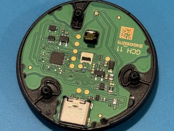
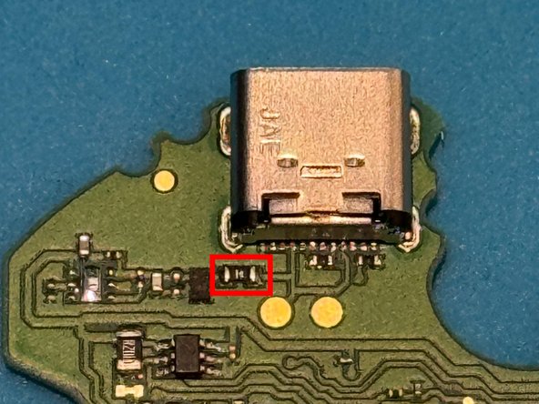
The fuse is next to the USB C port. The capacitor that gets burnt varies, but in my experience it is the bigger one (black colour) next to the fuse.
Do note the following:
- Usually both the fuse and the capacitor are burnt, you won't find the capacitor burnt without the fuse.
- If you do not have a 0402 fuse around and do not want to wait/do not care, you can just bridge the 2 contact points on the PCB and it will work the same way.
- To check which capacitor is burnt out, you will need to remove the capacitors 1 by one, and use a multimeter in Diode Mode to check for continuity. You must do this after each capacitor you remove until you see/hear the continuity/short stopped. I recommend starting with the capacitors very close to the USB C port, but those around the chip itself can also be the cause.
A regular soldering station is enough, but a hot air rework station would make it a lot easier and speed up things.
Follow the guide to disassemble the device and reassemble it after.
O que você precisa
-
-
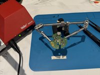
Start by placing the charger face down on a rubber mat or a surface that will help it not slip/move around.
-
Then use a plastic pry tool, or anything that has a very thin edge, to go around the rubber ring and reveal the screws. If you do it carefully with a very thin tool, you will leave no marks on the rubber ring.
-
Use a small screwdriver bit to remove the 3 screws. If I remember correctly they are T5 bits.
-
-
-
With the screws removed, the bottom cover of the case can be easily removed, there are no clips.
-
In order to remove the PCB, make sure to unclip the ribbon cable that goes to the wireless coil.
-
You can now separate all 3 parts, so you can work solely on the PCB.
-
-
-
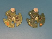
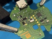
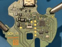
Do note that different models of chargers have different layouts. I had 3 chargers and all 3 were different models, with slight layout changes, but the actual parts and inner workings are the same.
-
-
-
-
I recommend putting the PCB on a surface that's antistatic. Or use some clips.
-
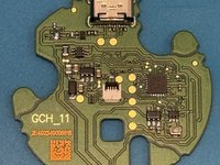
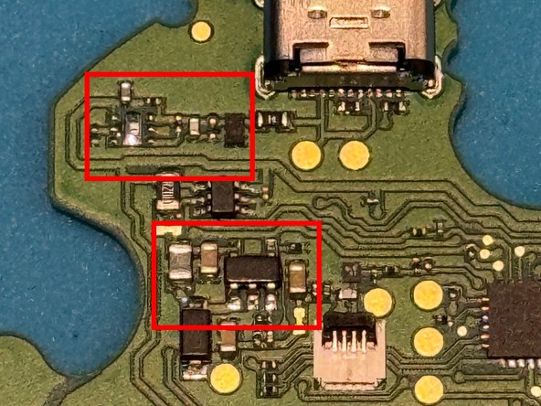
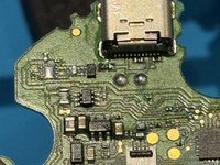
In the 3rd image I have added a red rectangle around the fuse. It is right below the USB C port, to the left, on all models.
-
Use a multimeter to check for continuity. If the multimeter in diode mode makes noise when touching the 2 ends of the fuse, then the fuse is fine. Othewise, it is burnt and it needs fixing.
-
The fuse usually burns out due to weird behaviours with chargers that also do 6V for output. Some chargers have 5V, 6V, 9V and 12V outputs. It will not fail immediately, but overtime.
-
-
-
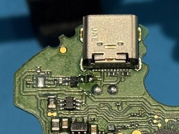
Use a soldering station and some tweezers to remove the fuse. I recommend using some flux too if available, to simplify the removal. A hot air station will make everything even simpler.
-
-
-
Take the new 0402 fuse with a pair of tweezers and solder it back in a similar manner to the removal of the old fuse.
-
If you do not have or want to use a fuse you can simply bridge the 2 contact points and it will work the same without issues. But it is better to be on the safer side by replacing it.
-
At this point you should use a multimeter on any of the capacitors present to check for a short/continuity. If you do not hear anything, then you can plug the charger in, and the white light should reappear, with the charger working well.
-
If you have plugged the charger in without checking for continuity, you will get a yellow/red/orange led, with the charging chip heating up, which means that there is a short on one of the capacitors. That's why I recommend first to check the continuity.
-
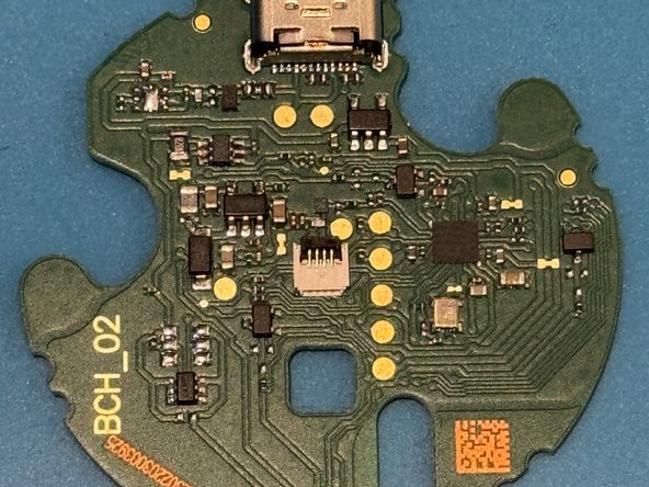
The second image has 2 red rectangles, any one of those capaciors could be burnt out. So what you have to do is remove them 1 by 1, until the short disappears, always checking with the multimeter. In my case, 1 charger was the fuse, one was that with the decoupling ceramic capacitor near the fuse (the black one). A 0.1uF 0603 SMD will do just fine.
-
-
-
You can now try the charger and it should work just fine.
-
This is a common issue on this charger so unless you use a 5V charger, you may run into this issue multiple times on all models.
-
Do note that the white light will turn off after a few seconds unless a ring is placed on top of the wireless coil and therefore, the charger is charging the ring (the white light goes to flashing/breathing). So do not worry if the light turns off while you are testing it after the repair, it is the intended behaviour.
-


To reassemble your device, follow these instructions in reverse order.
To reassemble your device, follow these instructions in reverse order.
