Esta versão pode conter edições incorretas. Mude para o último instantâneo verificado.
O que você precisa
-
Este passo não foi traduzido. Ajude a traduzi-lo
-
Locate the 2 screws on the bottom of the slider.
-
Remove both screws with a #00 Phillips screwdriver.
-
-
Este passo não foi traduzido. Ajude a traduzi-lo
-
Gently pull on the bottom of the slider until it comes off the lower track.
-
There is a little piece that connects the slider to the track. Be sure not to lose this as it is needed to put the slider back on.
-
-
Este passo não foi traduzido. Ajude a traduzi-lo
-
Lift the slider up until it comes off the upper track.
-
-
Este passo não foi traduzido. Ajude a traduzi-lo
-
The slider should now be free from the body of the camera.
-
-
Este passo não foi traduzido. Ajude a traduzi-lo
-
Locate the 3 screws on the outer metal band and remove them with a #00 Phillips screwdriver.
-
-
-
Este passo não foi traduzido. Ajude a traduzi-lo
-
Use the spudger to peel off the outer metal band, starting from the bottom of the camera.
-
-
Este passo não foi traduzido. Ajude a traduzi-lo
-
The shutter button can now be removed. It is not connected to the camera and can be lifted off.
-
-
Este passo não foi traduzido. Ajude a traduzi-lo
-
Remove the memory card.
-
Locate and remove the 2 screws using a #00 Phillips screwdriver.
-
-
Este passo não foi traduzido. Ajude a traduzi-lo
-
Use a spudger around the edge of the case to loosen it.
-
Carefully wiggle the back case off. This may require a fair amount of force.
-
-
Este passo não foi traduzido. Ajude a traduzi-lo
-
Locate the 3 internal screws holding on the front of the case. Remove them with a #00 Phillips screwdriver.
-
-
Este passo não foi traduzido. Ajude a traduzi-lo
-
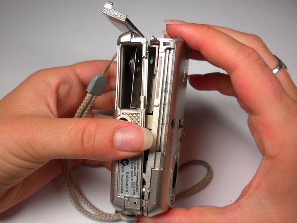
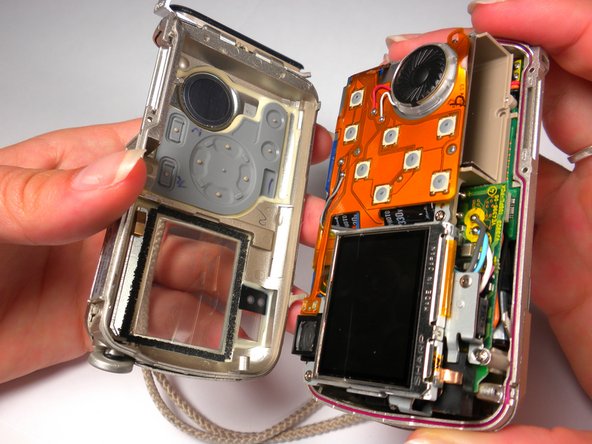
While grasping the interior and the front case, gently pull until they start to come apart. Some light wiggling may be required.
-
Be careful not to completely pull the front case off because it will still be connected with wires.
-
-
Este passo não foi traduzido. Ajude a traduzi-lo
-
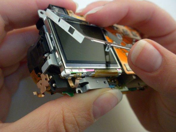
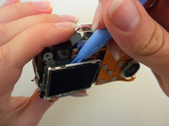
Remove the metal frame from the LCD screen using an opening tool.
-
-
Este passo não foi traduzido. Ajude a traduzi-lo
-
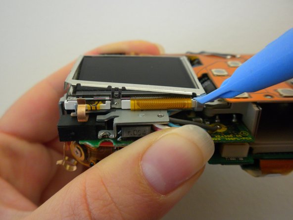
Pry off the LCD screen from the top using an opening tool.
-
-
Este passo não foi traduzido. Ajude a traduzi-lo
-
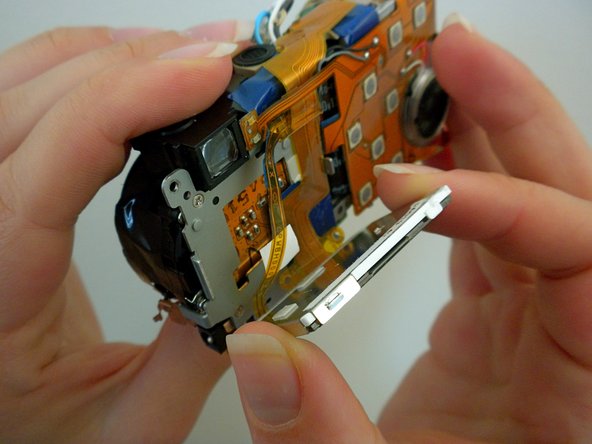
This is what the camera will look like now that the LCD screen is removed.
-


Equipe

Cal Poly, Team 6-13, Maness Spring 2010 Membro de Cal Poly, Team 6-13, Maness Spring 2010
CPSU-MANESS-S10S6G13
Membros da 5
Autoria de 17 guias