Esta versão pode conter edições incorretas. Mude para o último instantâneo verificado.
O que você precisa
-
Este passo não foi traduzido. Ajude a traduzi-lo
-
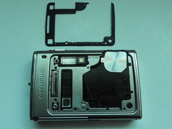
Using the iFixit Opening Tool, pry off the plastic part of the lens.
-
Using the T6 Torx screwdriver, unscrew the three screws.
-
-
Este passo não foi traduzido. Ajude a traduzi-lo
-
Using the Phillips #00 screwdriver, unscrew the three screws.
-
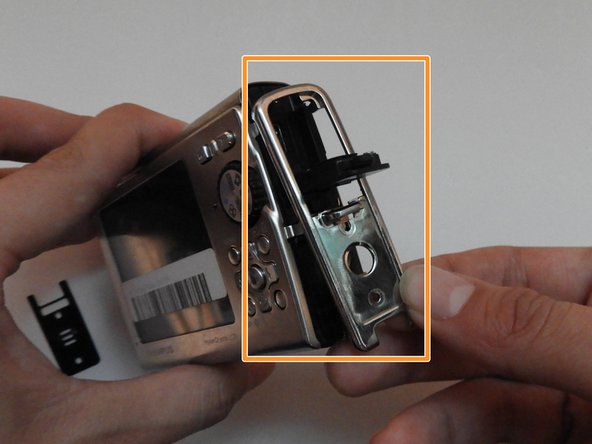
Carefully swivel the metal cover out towards you.
-
Using tweezers, remove the metal washer.
-
-
Este passo não foi traduzido. Ajude a traduzi-lo
-
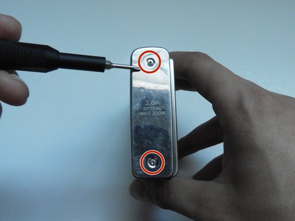
Using the Phillips #00 screwdriver, unscrew the two screws on the side of the camera.
-
-
Este passo não foi traduzido. Ajude a traduzi-lo
-
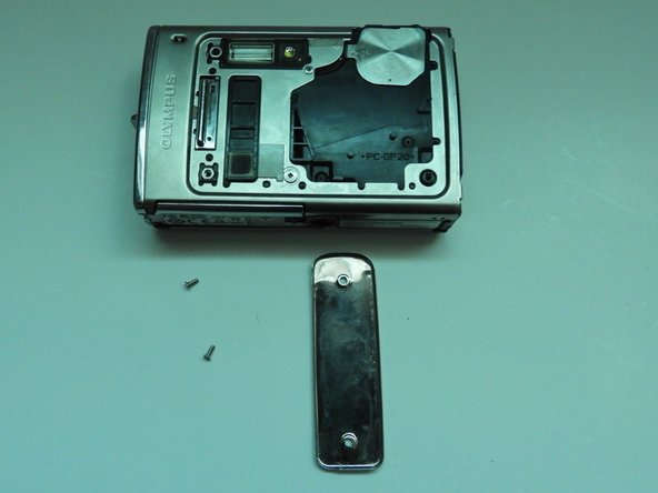
On the opposite side, use the Phillips #00 screwdriver to unscrew both screws.
-
Take out the speaker plate.
-
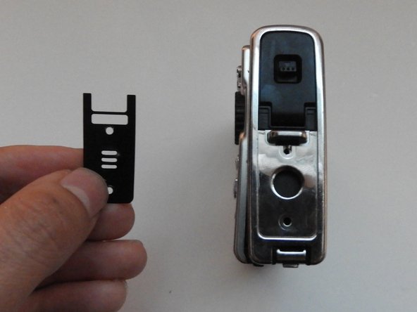
Open the multi-connector cover and slide off the side panel.
-
-
-
Este passo não foi traduzido. Ajude a traduzi-lo
-
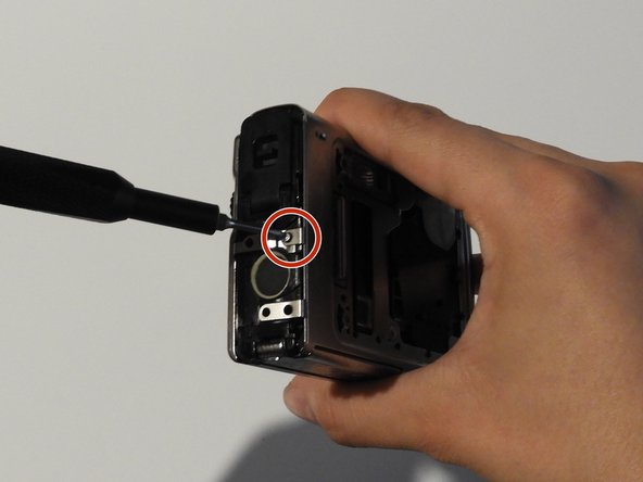
Using the Phillips #00 screwdriver, unscrew the screw above the speaker.
-
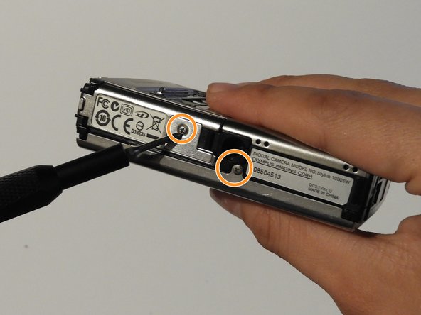
On the bottom side of the camera, unscrew the two screws.
-
-
Este passo não foi traduzido. Ajude a traduzi-lo
-
Open the battery compartment cover.
-
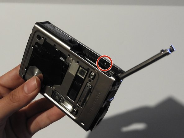
Use the Phillips #00 screwdriver to unscrew the screw in the battery compartment.
-
-
Este passo não foi traduzido. Ajude a traduzi-lo
-
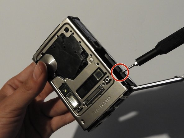
On the front of the camera, unscrew the two screws shown.
-
Gently pull on the side until the camera is separated from the back panel.
-
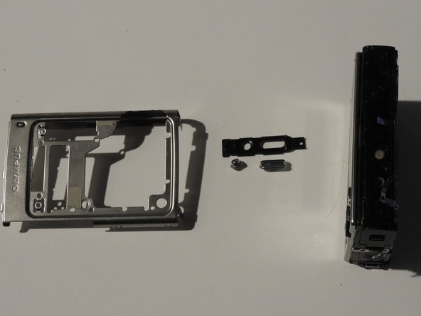
Remove the shutter and power button.
-
-
Este passo não foi traduzido. Ajude a traduzi-lo
-
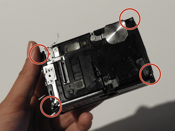
Use the Phillips #00 screwdriver to unscrew the four screws on the front of the camera.
-
Unscrew the shutter using the Phillips #00 screwdriver.
-
-
Este passo não foi traduzido. Ajude a traduzi-lo
-
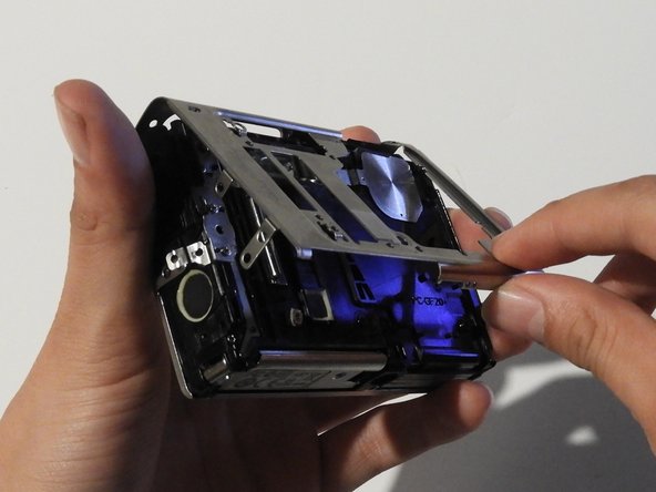
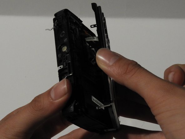
Release the top holding using a spudger.
-
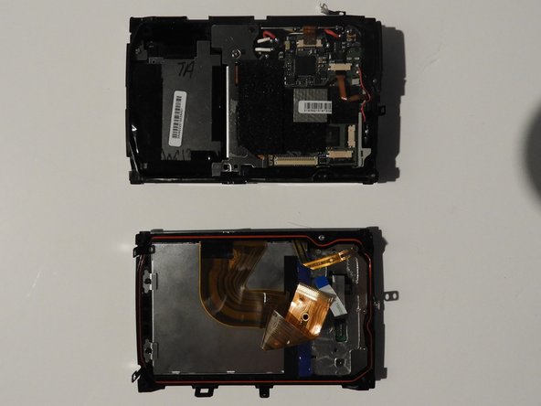
Slowly and carefully separate the front and back of the camera, exposing the electrical ribbons.
-
-
Este passo não foi traduzido. Ajude a traduzi-lo
-
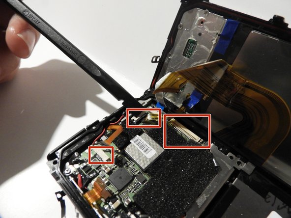
Using the spudger and tweezers if needed, remove the ribbons from the computer chips.
-
-
Este passo não foi traduzido. Ajude a traduzi-lo
-
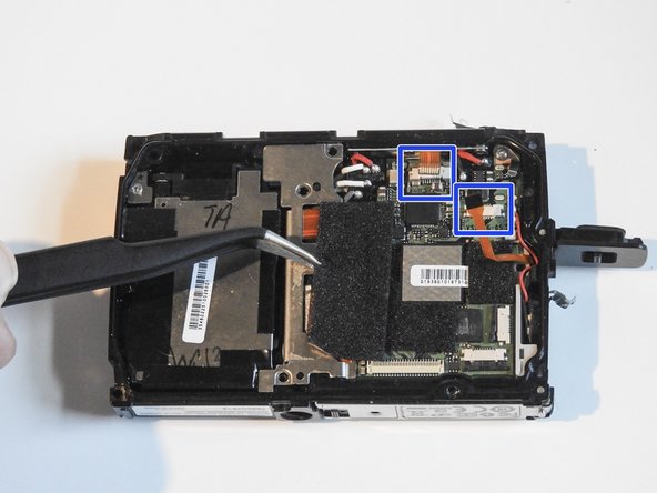
Remove the 1.0 cm and the 0.8 mm screws.
-
Peel off tape and remove ribbons.
-
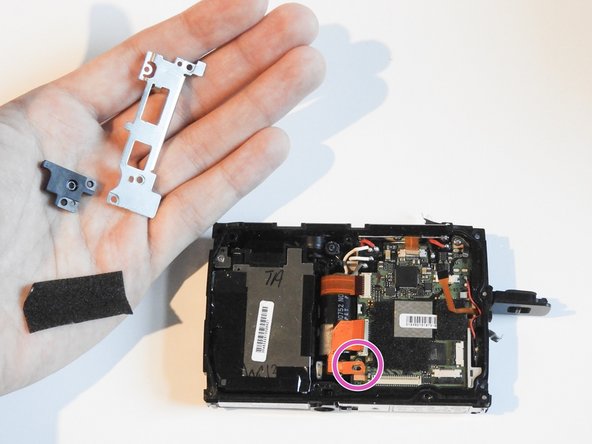
Remove black plastic cover and unscrew the 1.1 cm screw.
-
-
Este passo não foi traduzido. Ajude a traduzi-lo
-
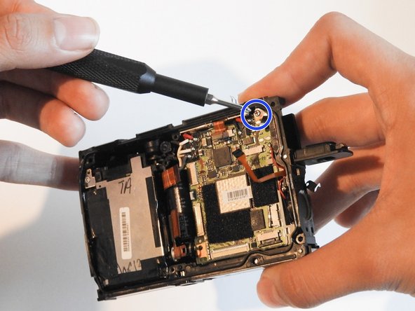
Release ribbons carefully using either tweezers or a spudger.
-
Remove the 1.1 cm screw.
-
-
Este passo não foi traduzido. Ajude a traduzi-lo
-
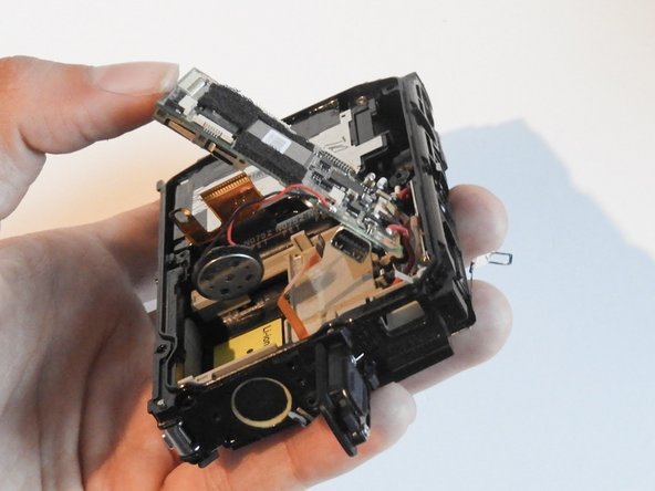
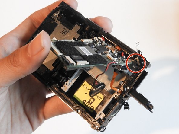
Push A/V port away from you carefully using a spudger.
-
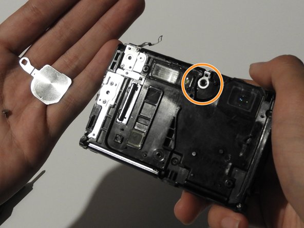
Slowly take out the motherboard and the speaker microphone.
-
Collect the metal washer plate from the top right corner of the motherboard (now loose).
-
-
Este passo não foi traduzido. Ajude a traduzi-lo
-
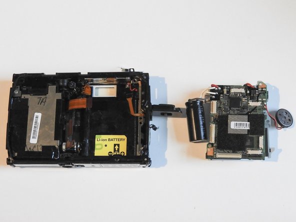
With a spudger or finger, slowly take out the battery hinged to the motherboard.
-
Take out motherboard.
-


Cancelar: não concluí este guia.
Uma outra pessoa concluiu este guia.
Equipe

University of Illinois Urbana-Champaign, Team 1-2, Scrogum Spring 2014 Membro de University of Illinois Urbana-Champaign, Team 1-2, Scrogum Spring 2014
UICU-SCROGUM-S14S1G2
Membros da 5
Autoria de 10 guias
3 comentários
How would I go about extracting the camera module and hooking it up to an arduino?
My cam got saltwater damage however it still turns on for a few seconds before turning off again